
Solid-liquid classification treatment device for metal cutting fluid recycling

A technology of metal cutting fluid and processing device, applied in the direction of filtration separation, separation method, filtration circuit, etc., can solve the problems of inability to separate the three for processing, and inability to recover cutting fluid, and achieve the effect of saving cutting fluid use and reducing costs.

Inactive Publication Date: 2021-09-07
南通友腾环保科技有限公司
View PDF0 Cites 0 Cited by
  • Summary
  • Abstract
  • Description
  • Claims
  • Application Information

AI Technical Summary

Problems solved by technology

[0003] In the prior art, the metal cutting fluid washes away the metal chips and also takes away the oil stains. Since the oil stains are also liquids, the cutting fluid cannot be recovered directly, and the three cannot be separated for processing, and when the recovered cutting fluid is not processed again, It does not use its characteristics for the initial treatment of metal workpieces, so a solid-liquid classification treatment device for metal cutting fluid recovery came into being

Method used


Image

  • Solid-liquid classification treatment device for metal cutting fluid recycling
  • Solid-liquid classification treatment device for metal cutting fluid recycling
  • Solid-liquid classification treatment device for metal cutting fluid recycling

Examples


Embodiment 1

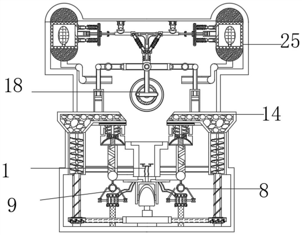
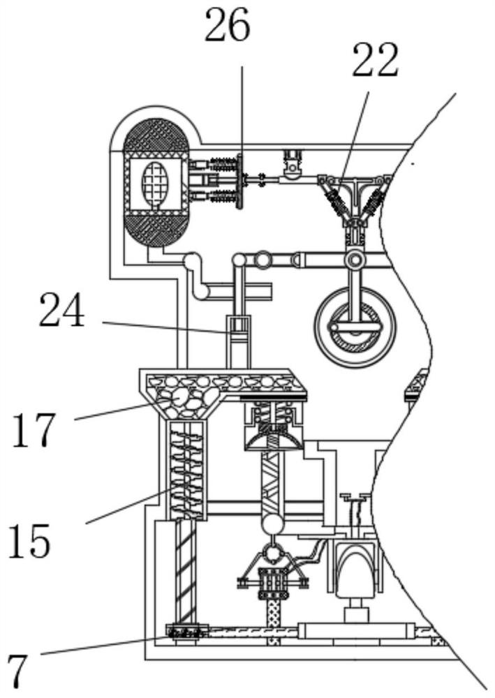
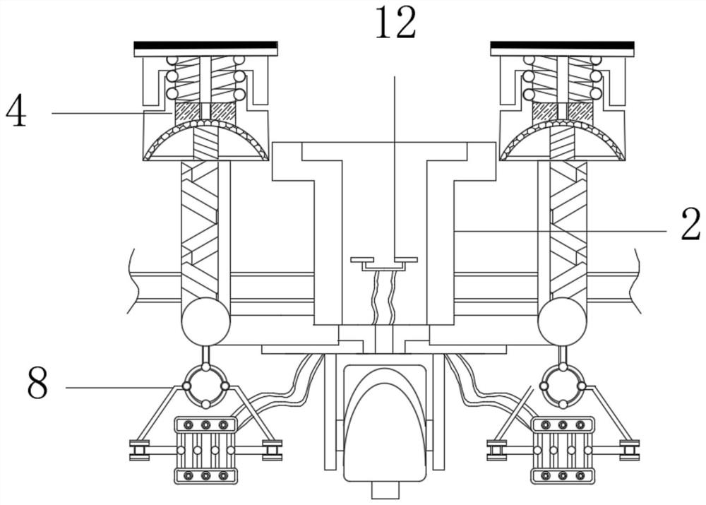
[0028] see figure 1 and 5 , a solid-liquid classification treatment device for metal cutting fluid recovery, including a static mechanism 1 and an oil suction mechanism 8, the static mechanism 1 includes a layered tank 2, and the left and right sides of the layered tank 2 are slidingly connected with drains The tube 3, the surface of the layered groove 2 is fixedly connected with the extension spring rod 4, the bottom of the layered groove 2 is fixedly connected with the cap 5, the inside of the cap 5 is movably connected with the rotating block 6, and the surface of the rotating block 6 is movably connected with the chain 7 .

[0029] Further, the oil suction mechanism 8 includes a display frame 9, the bottom of the display frame 9 is movably connected with a pull block 10, the inside of the pull block 10 is fixedly connected with a suction bag 11, and the top of the suction bag 11 is fixedly connected with a hose 12, and the top of the hose 12 A buoyancy plate 13 is fixedl...

Embodiment 2

[0032] see figure 1 and 6 , a solid-liquid classification treatment device for metal cutting fluid recovery, including a static mechanism 1 and an oil suction mechanism 8, the static mechanism 1 includes a layered tank 2, and the left and right sides of the layered tank 2 are slidingly connected with drains The tube 3, the surface of the layered groove 2 is fixedly connected with the extension spring rod 4, the bottom of the layered groove 2 is fixedly connected with the cap 5, the inside of the cap 5 is movably connected with the rotating block 6, and the surface of the rotating block 6 is movably connected with the chain 7 .

[0033] Further, the time difference mechanism 18 includes a cutting rotary knife 19, the front of the cutting rotary knife 19 is movably connected with a linkage rod 20, the surface of the linkage lever 20 is movably connected with a flat mouth plate 21, and the top of the flat mouth plate 21 is fixedly connected with a spring bar 22, and the spring ...

Embodiment 3

[0036] see Figure 1-8, a solid-liquid classification treatment device for metal cutting fluid recovery, including a static mechanism 1 and an oil suction mechanism 8, the static mechanism 1 includes a layered tank 2, the left and right sides of the layered tank 2 are slidingly connected with The drain pipe 3, the surface of the layered groove 2 is fixedly connected with the spring rod 4, the bottom of the layered groove 2 is fixedly connected with the cap 5, the inside of the cap 5 is movably connected with the rotating block 6, and the surface of the rotating block 6 is movably connected with The chain 7, the bottom of the stationary mechanism 1 is fixedly connected with the oil suction mechanism 8, the oil suction mechanism 8 includes a display frame 9, the bottom of the display frame 9 is movably connected with a pull block 10, the inside of the pull block 10 is fixedly connected with a suction bag 11, and the suction bag 11 The top is fixedly connected with a hose 12, and...


PUM


Abstract

The invention relates to the technical field of metal processing, and provides a solid-liquid classification treatment device for metal cutting fluid recycling. The solid-liquid classification treatment device comprises a standing mechanism and an oil suction mechanism, the standing mechanism comprises a layering groove, drainage pipes are slidably connected to the left side and the right side of the layering groove, and a tension spring rod is fixedly connected to the surface of the layering groove; a cap is fixedly connected to the bottom of the layering groove, a rotating block is movably connected into the cap, and a chain is movably connected to the surface of the rotating block. According to the solid-liquid classification treatment device for metal cutting fluid recycling, cutting fluid for flushing metal workpieces flows into a layering groove and stands, the effect of preliminary layering and convenient treatment is achieved, the layering groove stretches a tension spring rod to move so that a through opening can be in butt joint with a drainage pipe, and due to the fact that the through opening is higher than the bottom of the layering groove, and metal filings and the cutting fluid are separated through a filter screen, meanwhile, when the tension spring rod descends, the display rack is unfolded, the suction bag expands and sucks air, and layering separation is conducted through standing layering and gravity, so that mixing is avoided.

Description

technical field [0001] The invention relates to the technical field of metal processing, in particular to a solid-liquid classification processing device for recycling metal cutting fluid. Background technique [0002] Cutting fluid is an industrial liquid used in metal cutting and grinding to cool and lubricate cutting tools and workpieces. Easy to dilute, with the development of the times, production and life are inseparable from metal objects, metal processing is inseparable from metal cutting fluid, metal cutting fluid protects the shape and toughness of workpieces. [0003] In the prior art, the metal cutting fluid washes away the metal chips and also takes away the oil stains. Since the oil stains are also liquids, the cutting fluid cannot be recovered directly, and the three cannot be separated for processing, and when the recovered cutting fluid is not processed again, It does not use its characteristics for the initial treatment of metal workpieces, so a solid-liqu...

Claims


Application Information

Patent Timeline
IPC IPC(8): B01D36/04
CPCB01D36/04
Inventor 顾春健陈顺国章鹏程汤君君程敬宝
Owner 南通友腾环保科技有限公司
Learn More