
Self-locking method for nut and compression pitch deformation type self-locking nut

A self-locking nut and nut technology, applied in nuts, screws, bolts, etc., can solve the problems of unsatisfactory use effect of self-locking nut production process, large difference between locking torque and locking torque, and difficulty in tooling manufacturing. Achieve the effect of low production cost, slow decay of self-locking torque, and high reliability of self-locking

Inactive Publication Date: 2010-11-24
GUIZHOU AEROSPACE PRECISION PRODS
View PDF6 Cites 8 Cited by
  • Summary
  • Abstract
  • Description
  • Claims
  • Application Information

AI Technical Summary

Problems solved by technology

Most of the manufacturing process of closed-end self-locking nuts in the prior art is to process one end of the nut into a thinner elastic wall, and then perform elliptical (two-point compression), square (four-point compression) or triangular (three-point compression) Closing deformation, the closing tooling required by this closing method requires high precision and complex structure, which makes the tooling difficult to manufacture and inconvenient to use. Therefore, the closing process of this self-locking nut in the prior art has production The problem of low efficiency
In addition, the closed-end self-locking nuts in the prior art obtain the self-locking torque by compressing the thin-walled joint. Due to the weak resilience of the thin-walled closed joint, the locking torque decays quickly during use. The problem is that there is a large difference between the locking torque of the bolt screwed into the nut for the first time and the locking torque of screwing out. When the bolt is screwed in and out of the nut several times, the locking torque will rapidly decay.
Therefore, the existing self-locking nuts are not ideal either from the production process or from the use effect.

Method used


Image

  • Self-locking method for nut and compression pitch deformation type self-locking nut
  • Self-locking method for nut and compression pitch deformation type self-locking nut

Examples


Embodiment Construction

[0011] The present invention will be further described in detail below in conjunction with the accompanying drawings and embodiments.

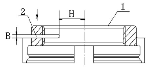
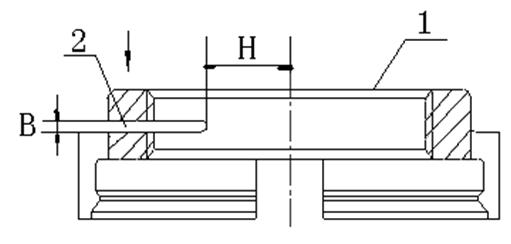
[0012] Embodiments of the present invention: when making self-locking nuts, preferably adopt a kind of self-locking method of nut of the present invention to design self-locking nuts, promptly on the surface of nut 1 with threaded holes, perpendicular to the central axis of nut 1 and Make at least one opening groove 2 communicating with the threaded hole along the radial direction of the threaded hole of the nut 1 (such as figure 1 shown), and then squeeze the nut 1 in the axial direction (such as figure 1 The direction indicated by the middle arrow), so that the width of the opening groove 2 is compressed and reduced, so that the pitch of the internal thread at the edge of the opening groove 2 of the nut 1 is locally deformed, and the pitch of the internal thread of the nut 1 is partially deformed. The nut 1 can be self-locked when it is con...


PUM


Abstract

The invention discloses a self-locking method for a nut and a compression pitch deformation type self-locking nut. In the invention, an open slot communicated with a threaded hole is at least reserved on the surface of the nut with the threaded hole in a manner of being vertical to the central axis of the nut and along the radial direction of the threaded hole of the nut; and the nut is extruded towards the axial direction to reduce the width of the open slot due to the compression, so that the internal-thread thread pitch at the edge position of the open slot of the nut generates partial deformation and the nut can be locked itself with the partial deformation generated by the internal-thread thread pitch of the nut when the nut is connected with a bolt. The self-locking nut has the advantages of simple structure, convenient manufacturing, high production efficiency, low manufacturing cost, slow self-locking force attenuation, good use effect, high self-locking reliability and the like.

Description

technical field [0001] The invention relates to a self-locking method of a nut and a self-locking nut in a compressed pitch modification form, belonging to the technical field of self-locking nuts. Background technique [0002] At present, metal type self-locking nuts in the prior art are mainly closed-type self-locking nuts, and the self-locking torque of these closed-type self-locking nuts is generated by changing (compressing) the pitch diameter of part of the thread of the nut. Most of the manufacturing process of closed-end self-locking nuts in the prior art is to process one end of the nut into a thinner elastic wall, and then perform elliptical (two-point compression), square (four-point compression) or triangular (three-point compression) Closing deformation, the closing tooling required by this closing method requires high precision and complex structure, which makes the tooling difficult to manufacture and inconvenient to use. Therefore, the closing process of this...

Claims


Application Information

Patent Timeline
Patent Type & Authority Applications(China)
IPC IPC(8): F16B39/284F16B37/00
Inventor 刘诗定蔡聪语周林李祥李燚
Owner GUIZHOU AEROSPACE PRECISION PRODS
Learn More