
Mold and method for foaming a cooling device

A technology of foam molding and refrigeration equipment, which is applied in the field of foam molding refrigeration equipment, and can solve problems such as deterioration of foam insulation effect

Inactive Publication Date: 2013-03-27
BOSCH SIEMENS HAUSGERATE GMBH
View PDF4 Cites 0 Cited by
  • Summary
  • Abstract
  • Description
  • Claims
  • Application Information

AI Technical Summary

Problems solved by technology

However, since air has a better thermal conductivity than carbon dioxide, the insulating effect of the foam deteriorates significantly

Method used


Image

  • Mold and method for foaming a cooling device
  • Mold and method for foaming a cooling device
  • Mold and method for foaming a cooling device

Examples


Embodiment Construction

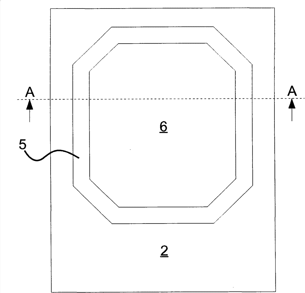
[0020] figure 1 with 2 The mold 1 shown in has a support plate 2 . The support plate 2 supports the rear wall 12 ( image 3 ) edges and corners.

[0021] The recess 3 is provided in the support plate 2 . This recess 3 has a depth slightly greater than 15 mm. The recess 3 has a flat bottom 4 and inclined side walls 5 . Unlike in the exemplary embodiment shown here, the transitions between the bottom 4 and the side walls 5 and between the side walls 5 and the support plate 2 can also be rounded.

[0022] Four spring barrels 7 are arranged in the recess 3 . The spring plates 6 are supported on these spring barrels 7 . The spring plate 6 can be pressed downwards onto the bottom 4 of the recess 3 with a predetermined force. The side edges of the spring plate 6 can be inclined such that in the pressed down state of the spring plate 6 they abut the side walls 5 of the recess 3 . However, a further recess with vertical side walls can also be provided in the bottom 4 of the re...


PUM


Abstract

The invention relates to a mold for foaming a cooling device supporting the rear wall (12) during the foaming process, having a support plate (2) corresponding to the rear wall (12). According to the invention, the support plate (2) comprises a recess (3) wherein a spring plate (6) is disposed, pressed by a supporting force in the starting position thereof, wherein the spring plate terminates flush with the support plate (2).

Description

technical field [0001] The invention relates to a mold and a method for foam molding a refrigeration device according to the preamble of claim 1 and according to the preamble of claim 6 . Background technique [0002] In refrigeration appliances, such as refrigerators or freezers, it is desirable to reduce energy consumption to a greater extent. To this end, new insulating materials are developed, the thermal conductivity of which has been reduced compared to that of conventional insulating materials. However, the use of new insulation materials is unaffordable and expensive because they cannot be processed using existing and conventional means and methods. [0003] Another option that has been considered is to increase the thickness of the insulating layer. However, this measure reduces the volume of internal space available for storing cooled food if the external dimensions of the refrigeration unit remain the same. [0004] Therefore, attempts have been made to increas...

Claims


Application Information

Patent Timeline
Patent Type & Authority Patents(China)
IPC IPC(8): B29C44/58B29C44/10
CPCB29C44/10B29C44/586
Inventor M·菲舍尔F·科尔敦M·雷施克R·施文克M·施魏尔
Owner BOSCH SIEMENS HAUSGERATE GMBH
Learn More