Magnetic bearing device, rotating mechanism, and model identification method of rotating machinery main unit

a technology of magnetic bearings and rotating mechanisms, which is applied in the direction of multiple dynamo-motor starters, dynamo-electric converter control, instruments, etc., can solve the problems of increasing the weight of the cable, increasing the workability of providing a magnetic bearing device, and many internal core wires of the dedicated cabl

Active Publication Date: 2010-06-15
EBARA CORP
View PDF20 Cites 20 Cited by
  • Summary
  • Abstract
  • Description
  • Claims
  • Application Information

AI Technical Summary

Benefits of technology

[0020]However, a dedicated cable supplies an electric power and a control signal for a magnetic bearing driving unit, a motor power, and so forth in a conventional structure including the structure proposed by the inventors in which a magnetic bearing main unit and a control device are separately placed. Consequently, a dedicated cable contains many internal core wires and has little flexibility because of its cable structure, and the weight of the cable increases. As a result, the workability for providing a magnetic bearing device is low.

Problems solved by technology

Consequently, a dedicated cable contains many internal core wires and has little flexibility because of its cable structure, and the weight of the cable increases.
As a result, the workability for providing a magnetic bearing device is low.
Selection between models having similar motor characteristics is difficult.
Therefore, such a model identification function cannot be workable for an already existing turbo-molecular pump to which no identification element has been provided.

Method used


Image

  • Magnetic bearing device, rotating mechanism, and model identification method of rotating machinery main unit
  • Magnetic bearing device, rotating mechanism, and model identification method of rotating machinery main unit
  • Magnetic bearing device, rotating mechanism, and model identification method of rotating machinery main unit

Examples


first embodiment

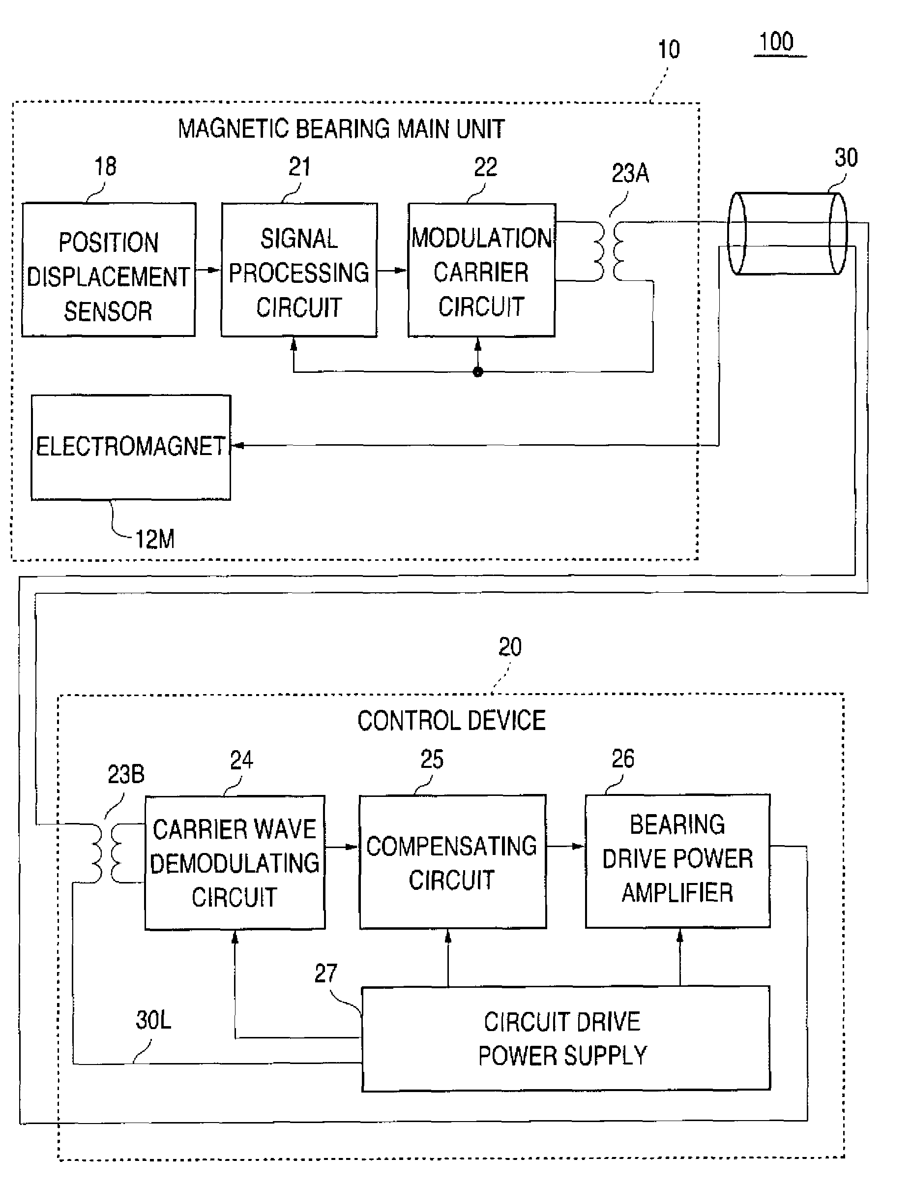
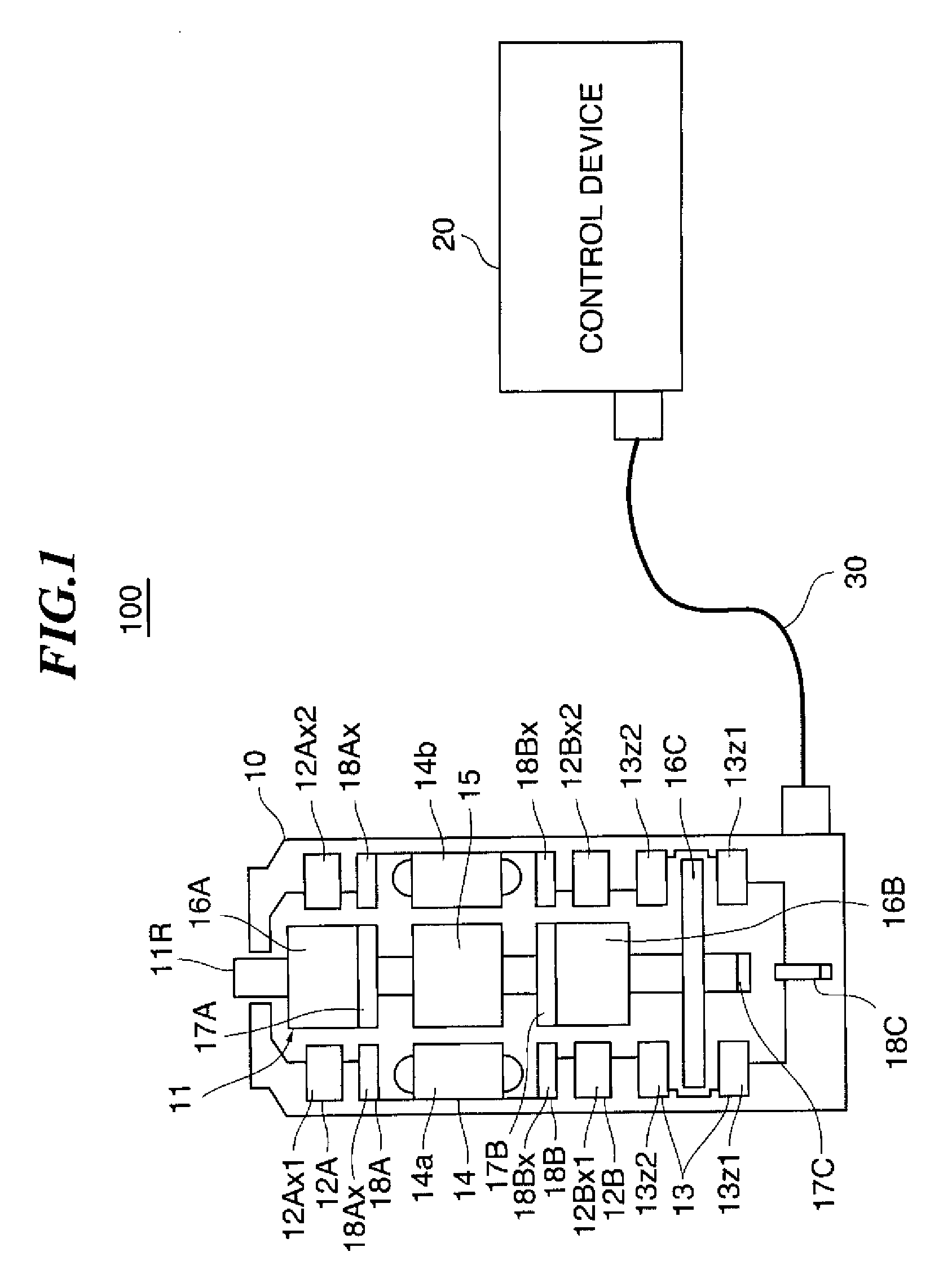
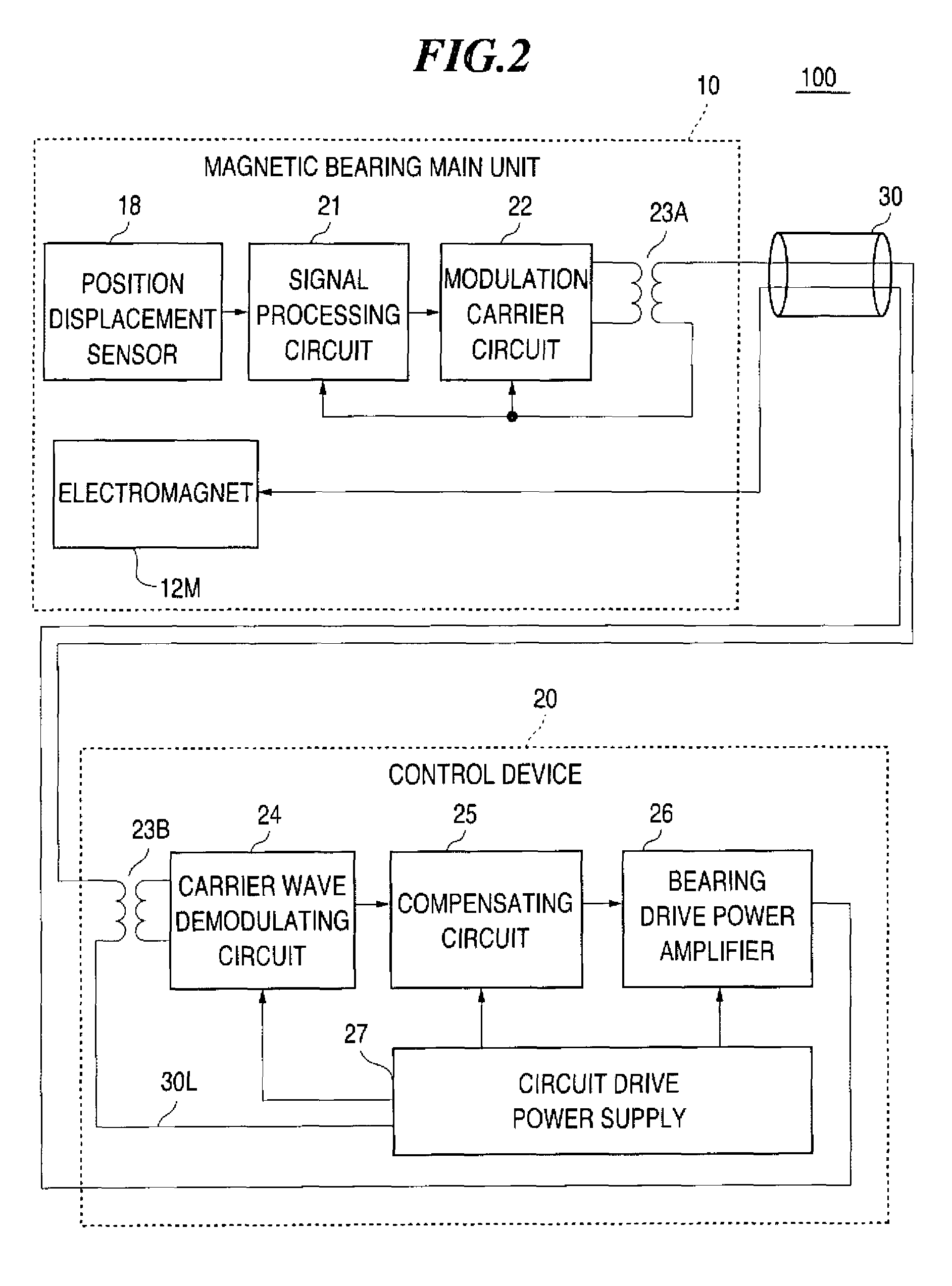
[0158]FIG. 1 shows an example of the constitution of the bearing mechanism of the magnetic bearing control system according to a first embodiment. In this embodiment, an example of a power line communication with an alternating-current coupling for transmitting the amount of the positional displacement detected by the displacement detection sensor will be described. A magnetic bearing device 100 includes the magnetic bearing main unit 10, the control device 20, and a dedicated cable 30 for connecting the magnetic bearing main unit 10 and the control device 20. The magnetic bearing main unit 10 accommodates the magnetic rotating body 11 from which one end of the rotational shaft 11R projects. The magnetic rotating body 11 is supported by the magnetic levitation resulted from two radial magnetic bearings 12A and 12B constituted with radial electromagnets and one axial magnetic bearing 13 constituted with an axial electromagnet. The motor 14 for rotatably driving the magnetic rotating ...

second embodiment

[0171]FIG. 3 is an example of a block diagram of a magnetic bearing device 100A according to a second embodiment. This is an example in which an analog-to-digital converter circuit 28 and a digital-to-analog converter circuit 29 are added for processing the signal between the magnetic bearing main unit 10 and the control device section 20 in the first embodiment.

[0172]The magnetic bearing main unit 10 is provided with the analog-to-digital converter circuit 28 between the signal processing circuit 21 and the modulation carrier circuit 22. The output of the signal processing circuit 21 is converted from the analog signal into the digital signal and output to the modulation carrier circuit 22. The modulation carrier circuit 22 modulates the carrier wave with the digital signal and generates the modulated wave for carrying the digital signal. The modulated wave is coupled with the power line by the first alternating-current coupling section 23A. In the control device 20, the modulated ...

third embodiment

[0175]FIG. 4 shows an example of a block diagram of a magnetic bearing device 100B according to a third embodiment. The power line communication using an alternating-current coupling is processed in one direction from the magnetic bearing main unit 10 to the control device 20 in the first embodiment. In the third embodiment, an example in which the power line communication is processed in both directions between the magnetic bearing main unit 10 and the control device 20 will be described. Specifically, the magnetic bearing main unit 10 has a first modulation carrier circuit 22A and the first alternating-current coupling section 23A, the control device 20 has the second alternating-current coupling section 23B and a first carrier wave demodulation circuit 24A, and the power line communication is executed from the magnetic bearing main unit 10 to the control device 20 in a first electricity supply line 30LA. In addition, the control device 20 has a second modulation carrier circuit 2...


PUM


Abstract

Problem of the present invention is to enable elimination or reduction of a signal wire in a dedicated cable for a magnetic bearing device for supplied an electric power from a control device to a magnetic bearing main unit via the dedicated cable. A magnetic bearing device 100 according to the present invention has a magnetic bearing main unit 10 having an electromagnet 12M for magnetically levitating and rotatably supporting a magnetic rotating body 11 and functioning as a magnetic bearing, a control device 20 having a compensating circuit 25 for generating a control signal for controlling a levitation position of the magnetic rotating body 11, and an electricity supply line 30L for supplying an electric power from the control device 20 to the magnetic bearing main unit 10. The magnetic bearing main unit 10 has a modulation carrier circuit 22 for generating a modulated wave and a first alternating-current coupling section 23A for transmitting the generated modulated wave to the control device 20 by the alternating-current coupling with the electricity supply line 30L. The control device 20 has a second alternating-current coupling section 23B for separating the modulated wave alternating-current coupled from the electricity supply line 30L and a carrier wave demodulating circuit 24 for detecting the separated carrier signal wave.

Description

BACKGROUND OF THE INVENTION[0001]1. Technical Field[0002]The present invention relates to a magnetic bearing device, a rotating mechanism, and a model identification method of a magnetic bearing main unit or a rotating machinery main unit. More particularly, the present invention relates to the magnetic bearing device for transmitting a signal between the magnetic bearing main unit and a control device by a power line communication with an alternating-current coupling. In addition, the present invention relates to the model identification method of the magnetic bearing main unit of the magnetic bearing device or the rotating machinery main unit of the rotating mechanism of a constitution in which the control device (the control device set with a control condition optimal for each model) having a different control condition according to each model is connected via a dedicated cable with the magnetic bearing main unit or the rotating machinery main unit for supporting a rotating body ...

Claims


Application Information

Patent Timeline
Patent Type & Authority Patents(United States)
IPC IPC(8): H02K7/09H02K11/00
CPCF16C32/0444F16C41/008F16C32/0489F16C2360/45
Inventor OYAMA, ATSUSHI
Owner EBARA CORP
Why Eureka
Try Eureka