
Thermal management for an electric or hybrid vehicle and a method for air-conditioning the interior of such a motor vehicle

a technology of electric or hybrid vehicles and management systems, which is applied in the operation mode of machines, lighting and heating apparatus, transportation and packaging, etc., can solve the problems of reducing the possible range of electric operation, little waste heat of combustion or electric drive available for other purposes, etc., and achieves high energy efficiency and improved thermoelectric module efficiency.

Active Publication Date: 2016-10-13
GENTHERM GMBH +2
View PDF27 Cites 23 Cited by
  • Summary
  • Abstract
  • Description
  • Claims
  • Application Information

AI Technical Summary

Benefits of technology

The patent describes a thermal management system for electric vehicles that includes two coolant circuits with different temperature levels. The first, high-temperature coolant circuit cools the electric powertrain, while the second, low-temperature coolant circuit cools the interior of the vehicle. The low-temperature circuit has a maximum operating temperature of 40-50 °C, which is ideal for cooling the interior. The system also includes a separate heating circuit that allows for efficient use of available power sources and can be used for heating purposes to provide peak power and adjust the temperature of the interior air. The parallel operation of both the burner and the temperature control device during transient operation improves comfort and helps to defrost the vehicle at startup. The system also allows for improved energy-efficient use of the vehicle's power sources.

Problems solved by technology

For electric or hybrid vehicles in general, the problem is that compared to conventional internal combustion engines, only little waste heat of the combustion or electric drive is available to be used for other purposes, in particular for heating the passenger compartment.
Drawing on the electrical energy available for heating or cooling purposes regularly reduces the possible range in electric operation.

Method used


Image

  • Thermal management for an electric or hybrid vehicle and a method for air-conditioning the interior of such a motor vehicle
  • Thermal management for an electric or hybrid vehicle and a method for air-conditioning the interior of such a motor vehicle
  • Thermal management for an electric or hybrid vehicle and a method for air-conditioning the interior of such a motor vehicle

Examples


Embodiment Construction

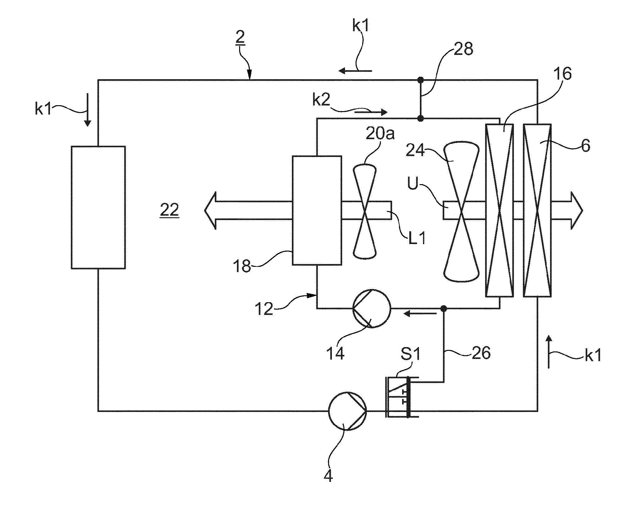
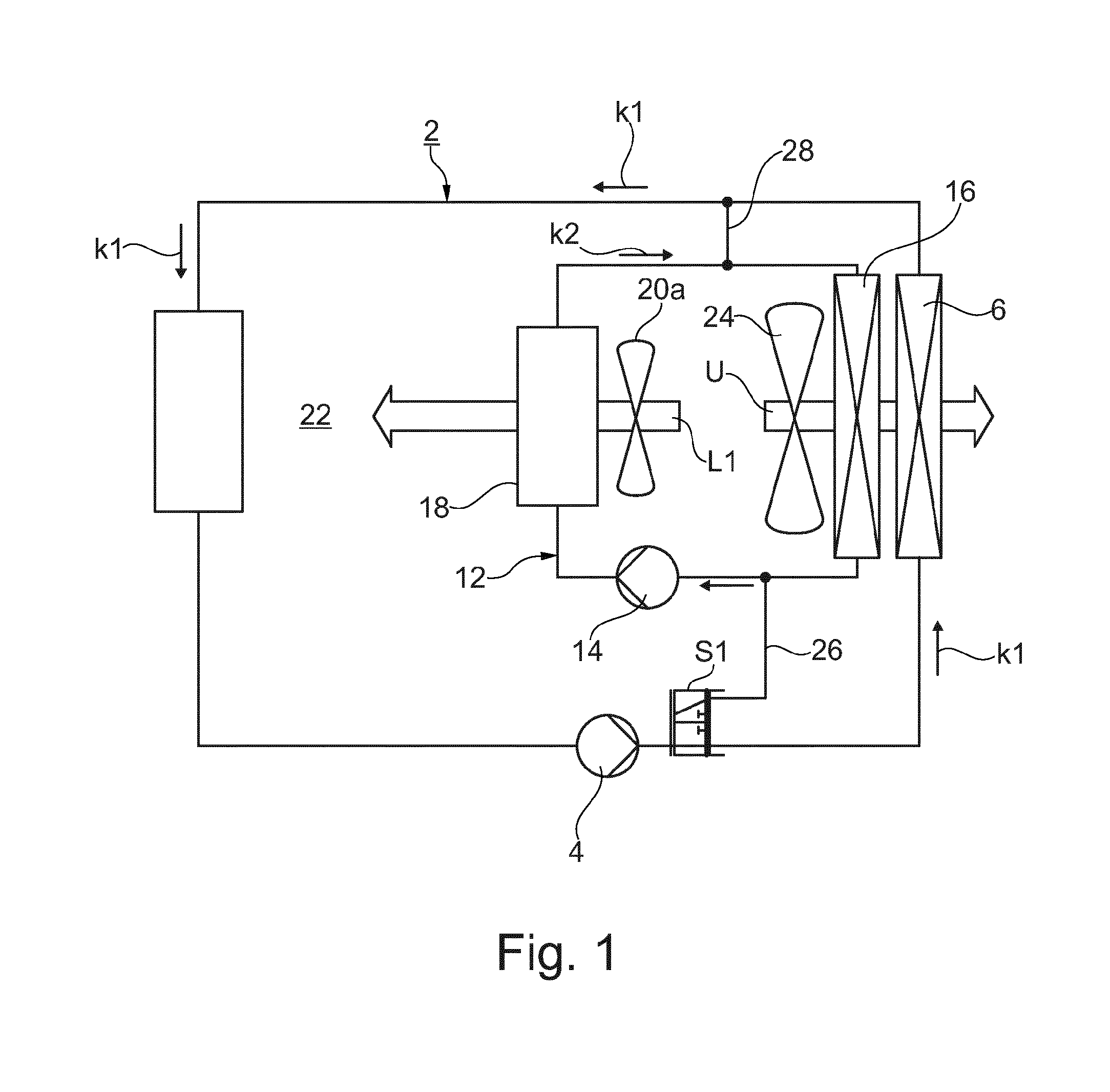
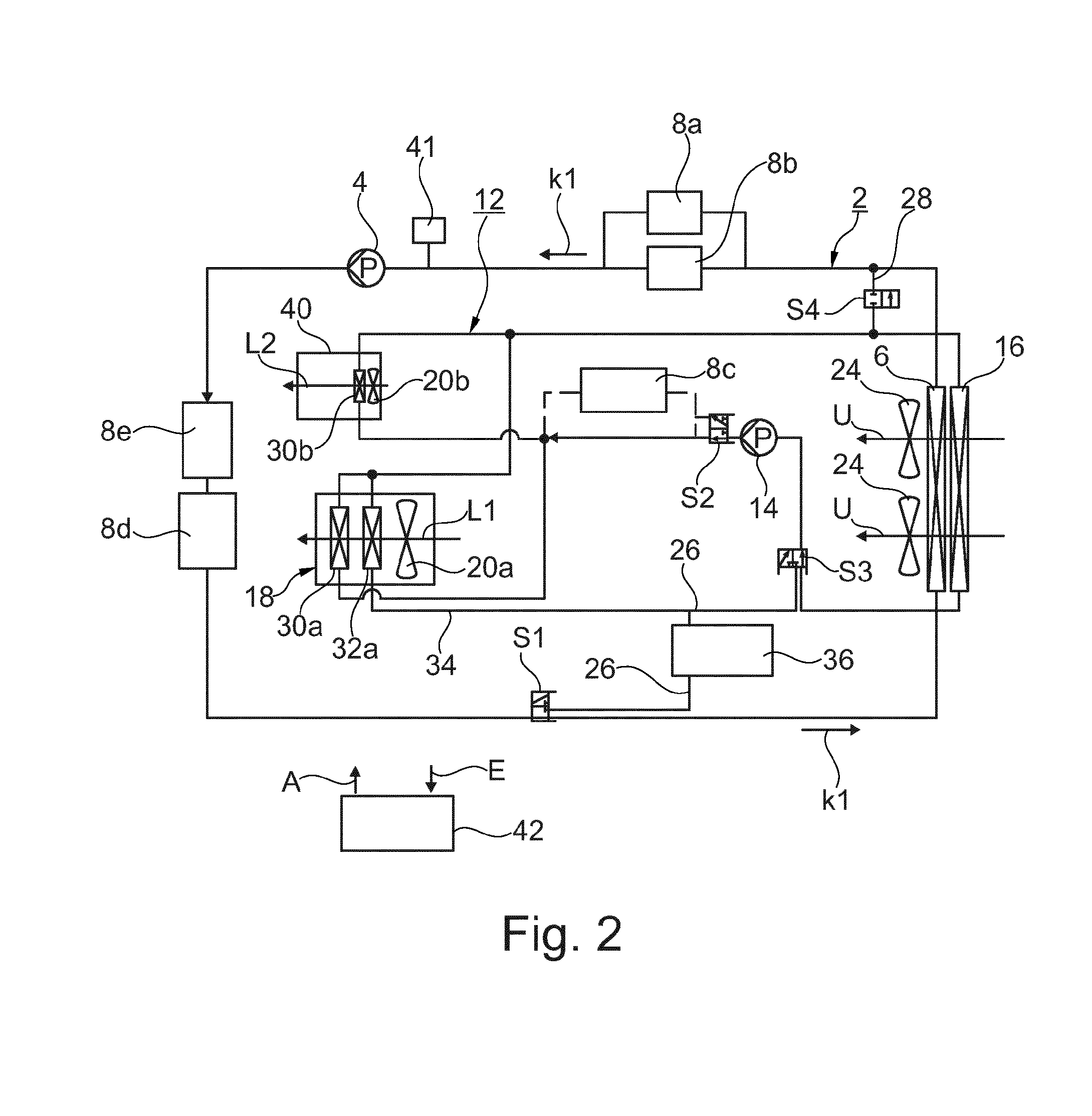
[0039]The basic structure of the thermal management system is explained in detail with reference to FIG. 1: The thermal management system comprises a first coolant circuit 2, in which a liquid first coolant K1 is cycled, as indicated by the arrows. The first coolant circuit is hereinafter referred to as HT coolant circuit 2. A first pump 4, a first ambient heat exchanger 6 and at least one component of an electric powertrain 8 to be cooled are integrated in the HT coolant circuit 2. The electric powertrain 8 thereby forms a heat source and the first ambient heat exchanger 6 is a heat sink.

[0040]The thermal management system additionally comprises a second coolant circuit 12, which is hereinafter referred to as NT cooling cycle 12. For better differentiation, the HT coolant circuit 2 is shown in the figures with a thicker line width. A second liquid coolant K2 is cycled in the NT coolant circuit 12. The second coolant circuit 12 for this purpose comprises a second pump 14, a second a...


PUM


Abstract

An energy-efficient thermal management system for an electric or hybrid vehicle is provided. The system has a first coolant circuit for controlling the temperature of electric components of an electric powertrain, an air-conditioning unit being provided for air-conditioning an interior. A second coolant circuit air-conditions the interior and is operable independently of the first coolant circuit. Each coolant circuit comprises a pump and a respective ambient heat exchanger. In order to control the temperature of the interior, a temperature control device which can be designed as a Peltier module is integrated into the second coolant circuit, said temperature control device operating in the manner of a heat pump for heating purposes. The two coolant circuits can be coupled to each other in order to exchange heat. An additional temperature control device can be integrated in order to air-condition an interior component in a decentralized manner, in particular a seat.

Description

[0001]This nonprovisional application is a continuation of International Application No. PCT / EP2014 / 078777, which was filed on Dec. 19, 2014, and which claims priority to German Patent Application No. 10 2013 227 034.8, which was filed in Germany on Dec. 20, 2013, and which are both herein incorporated by reference.BACKGROUND OF THE INVENTION[0002]1. Field of the Invention[0003]The invention relates to a thermal management system for an electric or hybrid vehicle. The invention further relates to a method for air-conditioning the interior of a motor vehicle with such a thermal management system.[0004]2. Description of the Background Art[0005]Such a thermal management system is disclosed for example in WO 2011 / 029538 A1.[0006]For electric or hybrid vehicles in general, the problem is that compared to conventional internal combustion engines, only little waste heat of the combustion or electric drive is available to be used for other purposes, in particular for heating the passenger c...

Claims


Application Information

Patent Timeline
Patent Type & Authority Applications(United States)
IPC IPC(8): B60H1/00F25B21/04
CPCB60H1/00478F25B21/04B60H2001/00307B60H1/00385B60H1/00278F25B21/02F25B2700/21153
Inventor RIEDERER, STEFANHOERTH, LEONHARDBIRNDORFER, HEINRICHRANALLI, MARCOADLDINGER, MARTINLORENZ, MANUEL
Owner GENTHERM GMBH
Learn More