Circuit breaker and current transformer for corresponding circuit breaker

A technology of current transformers and circuit breakers, applied in the direction of inductors, variable inductors, circuits, etc., can solve problems such as insufficient limits

Active Publication Date: 2010-03-31
SUZHOU SIEMENS ELECTRIC APPLIANCE
View PDF1 Cites 20 Cited by
  • Summary
  • Abstract
  • Description
  • Claims
  • Application Information

AI Technical Summary

Problems solved by technology

[0004] The downside: this restriction is often not enough

Method used


Image

  • Circuit breaker and current transformer for corresponding circuit breaker
  • Circuit breaker and current transformer for corresponding circuit breaker
  • Circuit breaker and current transformer for corresponding circuit breaker

Examples


Embodiment Construction

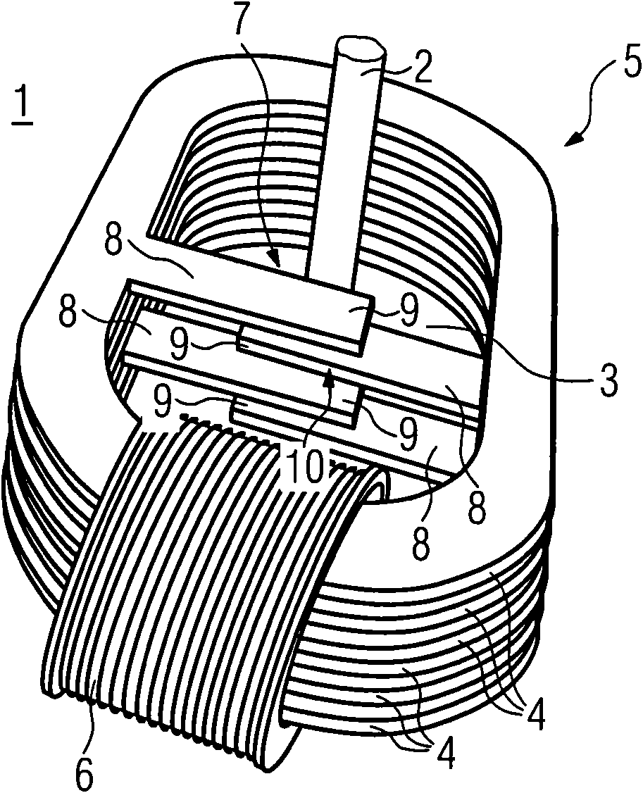
[0024] figure 1 Shown is a current transformer 1 for a disconnecting device of a circuit breaker (not shown), which in an emergency breaks the current (primary current) flowing through the conductor 2 and thus through the circuit breaker, in order to protect circuit (not shown), which is powered by means of the primary current.

[0025] The electronic disconnection device disconnects the primary current, wherein the electronic disconnection device is supplied via a current transformer 1 , which outputs from a conductor 2 (primary conductor) the electrical energy required to couple the disconnection device.

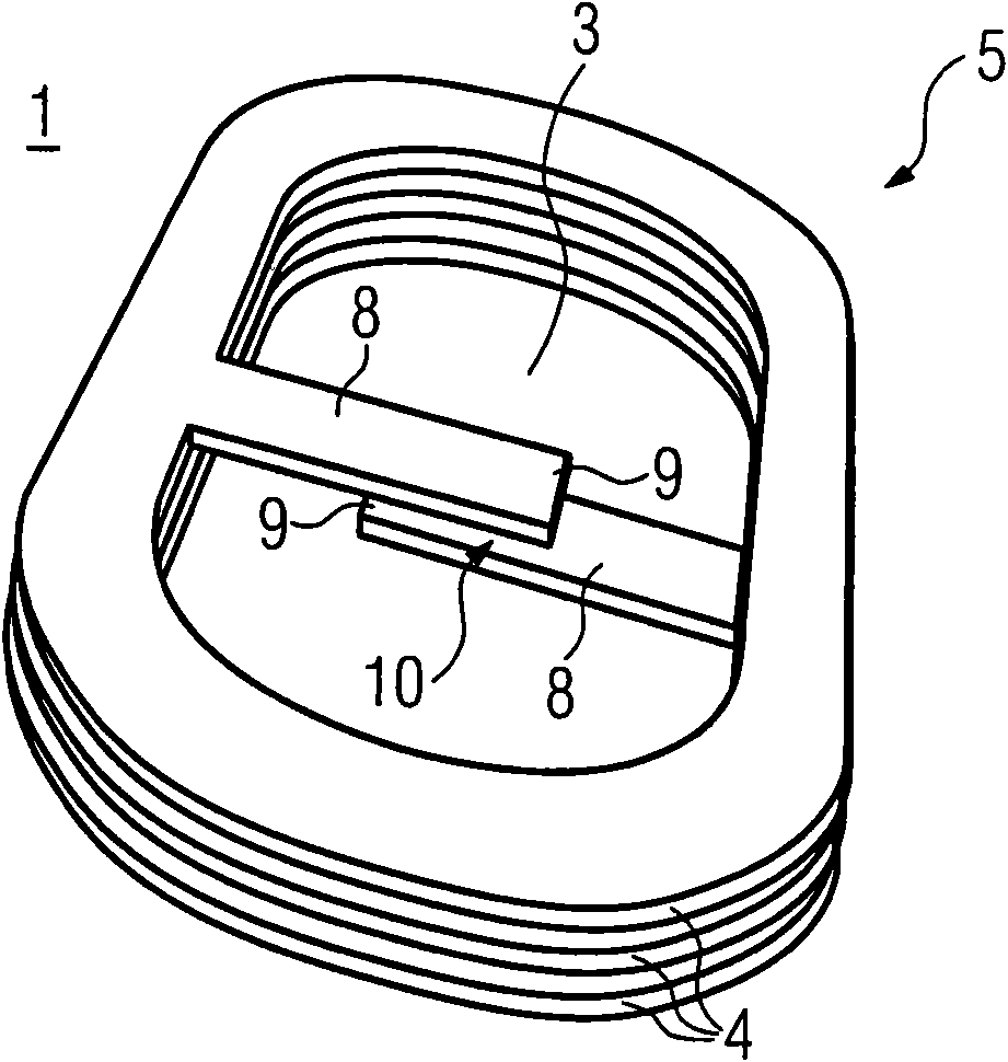
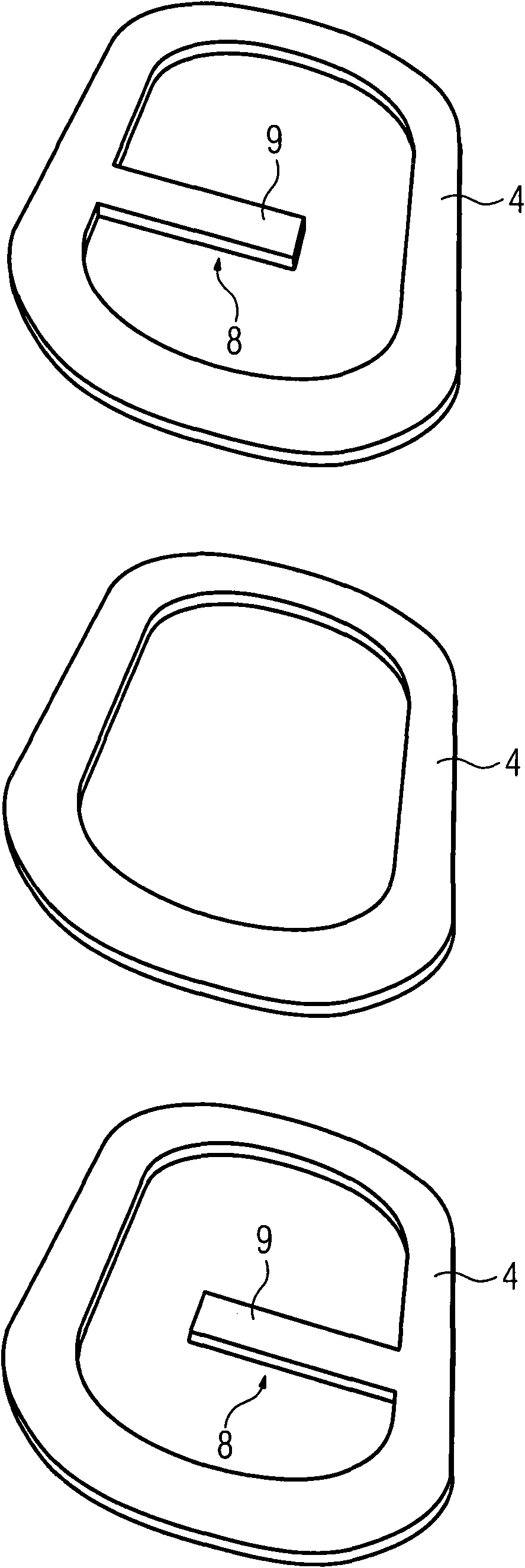
[0026] Such as figure 1 As shown, the conductor 2 is guided through an opening 3 (through a ring having the opening 3 ), which is formed of soft magnetic foils 4 stacked one above the other, which form the main magnetic circuit 5 . (The main magnetic circuit 5 can also be made of ferrosilicon with oriented or non-oriented grains, or other crystalline, amorphous or nanocr...


PUM


Abstract

The present invention relates to a circuit breaker and a current transformer (1) for the corresponding circuit breaker, wherein the circuit breaker is used for disconnecting primary current that passes in a conductor; the primary current supplies electricity to the circuit needed protecting, wherein a disconnecting device for disconnecting is provided, and wherein the current transformer (1) supplies electricity to the disconnecting device, and the current transformer (1) is provided with a main magnetic circuit (5) passing around the conductor (2), and at least a secondary winding (6) with an iron core formed by a part of the main magnetic circuit (5). A magnetic branch (7) is mounted in parallel to the core of the secondary winding (6), wherein the branch has additional magnetic resistance. The additional magnetic resistance is reduced automatically for current higher than rated current of the breaker, in case of short circuit, by magnetic forces producing in the branch to obtain anefficient reduction of magnetic resistance in the parallel branch (7).

Description

technical field [0001] The invention relates to a circuit breaker for breaking a current flowing through conductors and a current transformer for a corresponding circuit breaker according to the preambles of claims 1 and 12 . Background technique [0002] Circuit breakers for breaking electrical current are well known. Here, the current that needs to be broken flows through the circuit breaker itself; the circuit that needs to be protected is powered through the conductors on the output side. The disconnecting device is used for disconnection, and the device is supplied with electrical energy via a current transformer (core transformer), wherein the electrical energy comes from the current flowing through the conductor (primary current). One such disconnect device is disclosed by EP0704867B1. Its current transformer also has a main magnetic circuit consisting of an iron core, through which the conductor is led, which may form a "primary winding". The main magnetic circuit...

Claims


Application Information

Patent Timeline
Patent Type & Authority Applications(China)
IPC IPC(8): H01H71/00H01H83/00H01F38/28
CPCH01F29/10H01F3/14H01F38/30H01H71/125
Inventor 马库斯·格罗斯托马斯·金德尔
Owner SUZHOU SIEMENS ELECTRIC APPLIANCE
Why Eureka
Try Eureka