Medical suture needle

A suture needle and medical technology, applied in the field of medical suture needles, can solve the problems of metal wire breakage, breakage, etc., and achieve the effect of improving fragility, improving thread fragility, and improving fragility

Inactive Publication Date: 2010-12-08
MATSUTANI SEISAKUSHO CO LTD
View PDF1 Cites 6 Cited by
  • Summary
  • Abstract
  • Description
  • Claims
  • Application Information

AI Technical Summary

Problems solved by technology

However, when this technology is directly applied to the combination of a medical suture needle and a metal wire, there is a problem that the metal wire is easily broken from the vicinity of the hole formed on the base end surface of the medical suture needle.
[0007] That is, if Figure 5 As shown, after inserting the end portion of the thread 52 into the blind hole 51b formed in the base end surface 51a of the suture needle 51 and applying an equal force to the outer periphery of the base end portion 51c to compress it, the suture needle 51 is fixed by pliers or the like. In the last state, the wire 52 is repeatedly bent 180 degrees in a manner of 90 degrees relative to the base end surface 51a, and there is a problem of breakage when performing one reciprocation or two reciprocations.

Method used


Image

  • Medical suture needle
  • Medical suture needle
  • Medical suture needle

Examples


Embodiment 1

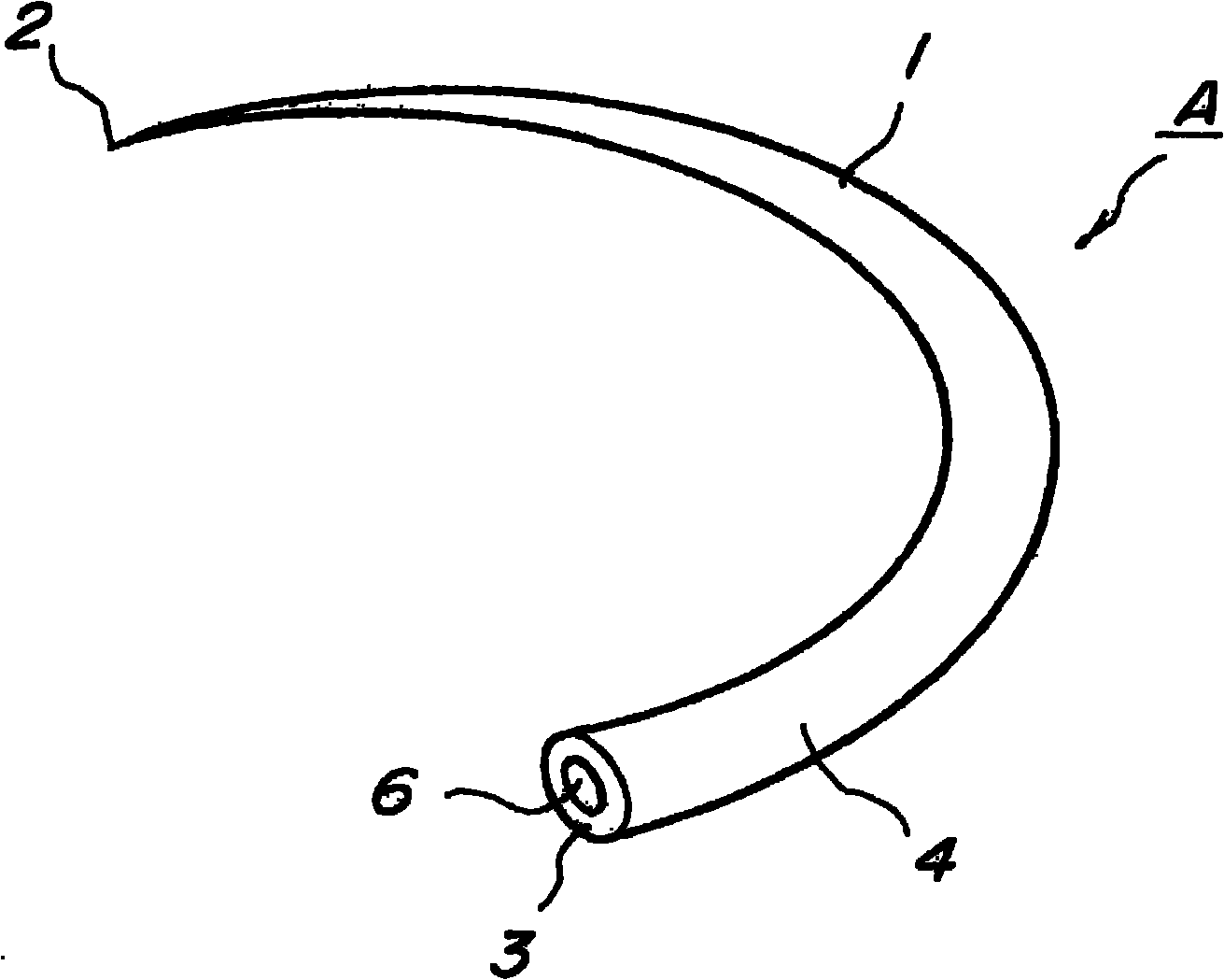
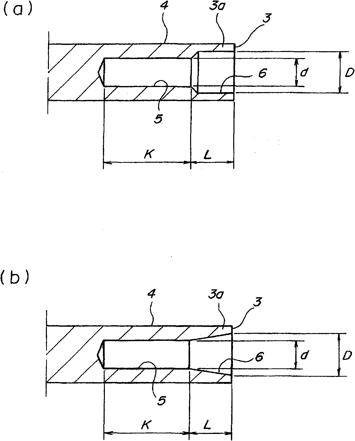
[0040] Next, the structure of the suture needle according to this embodiment will be described with reference to the drawings. figure 1 It is a figure explaining the whole structure of a suture needle. figure 2 It is a cross-sectional view of the base end portion of a suture needle, and is a diagram illustrating the structure of a blind hole and a countersink hole.

[0041] figure 1 The shown medical suture needle A is a suture needle that pierces the bone when suturing the bone. The other end is formed with a base end face 3 . In addition, the base end surface 3 side of the needle body 1 is formed as a base end portion 4 .

[0042] In this embodiment, the cross section of the needle body 1 is formed in a circle, but it is not limited to this cross section shape, and may be formed in a polygonal shape including a triangle in cross section, and a blade is formed on any edge. In addition, the needle point 2 is not limited to a sharp point, but may be a so-called blunt nee...

Embodiment 2

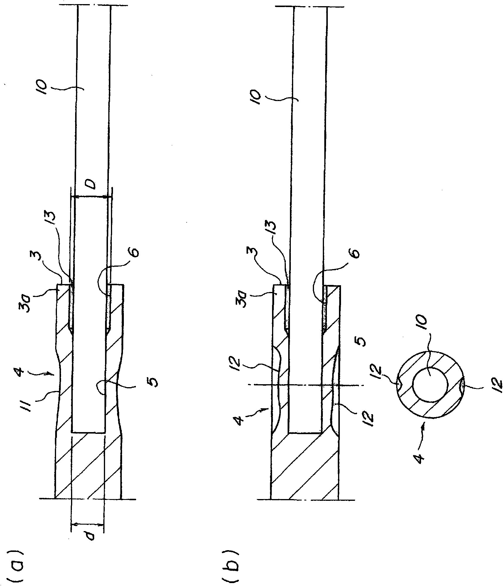
[0055] Next, the above-mentioned experimental results will be described, and prior to the description, the structure of the threaded suture needle according to this embodiment will be described with reference to the drawings. image 3 It is a diagram illustrating a state in which a thread is combined with a blind hole formed in a suture needle. Figure 4 It is a figure explaining the state which carried out the bending test of the thread|yarn bonded to the suture needle. In addition, in the figure, the same code|symbol is attached|subjected to the same part as the above-mentioned Example, and it demonstrates.

[0056] In the suture needle with thread (medical suture needle) according to the present invention, a blind hole and a countersink are formed on the base end surface of the suture needle configured to be able to pierce bone, and a metal thread 10 is integrally integrated with the blind hole. . In the present invention, it is necessary to form a blind hole and a counte...


PUM


Abstract

This aims to reduce a problem that a metal wire joined integrally to a hole formed in the root end face of a medical suture needle is liable to break. A suture needle (A) comprises a stop hole (5) formed in a root end face (3) for joining the end portion of a wire (10) by inserting and caulking the same, and a counter bore (6) formed on the side of the root end face (3) of the stop hole (5) and having a larger size (D) at least on the root end face (3) than the size (d) of the stop hole (5) and a smaller depth (L) than that of the caulking portion of the stop hole (5). The wired suture needle joins the wire (10) integrally by inserting the end portion of the wire (10) into the stop hole (5) and by caulking the outer circumference corresponding to the stop hole (5).

Description

technical field [0001] The present invention relates to an advantageous medical suturing needle for use in suturing bones including the sternum. Background technique [0002] When suturing the bones, including the sternum, it is done with wire. Then, the metal wire is integrated with the proximal end of the medical suture needle, the medical suture needle is used to pierce the bone to pass the metal wire together, and the target site is sutured by binding the metal wire that has passed through the bone. [0003] The bonding of the metal wire to the medical suture needle is carried out as follows: a hole larger than the thickness of the metal wire is formed on the base end surface of the medical suture needle, the end of the metal wire is inserted into the hole, and the outer circumference corresponding to the hole is Partially compressed and reduced in diameter. If the bonding strength when the metal wire and the medical suture needle are integrated is too weak, the metal ...

Claims


Application Information

Patent Timeline
Patent Type & Authority Applications(China)
IPC IPC(8): A61B17/06
CPCA61B17/06004A61B2017/06028A61B17/06066A61B2017/06033
Inventor 松谷正明福田祥一福田正俊阿久津真一加藤一明矢野真一
Owner MATSUTANI SEISAKUSHO CO LTD
Why Eureka
Try Eureka