
Clamping device for processing roller

A clamping device and plate roller technology, applied in positioning devices, metal processing equipment, metal processing machinery parts, etc., can solve the problems of high technical requirements for employees and inconvenient adjustment, and achieve the effect of convenient loading and unloading of workpieces

Inactive Publication Date: 2012-03-21
SHANGHAI YUNAN PLATE MAKING
View PDF0 Cites 0 Cited by
  • Summary
  • Abstract
  • Description
  • Claims
  • Application Information

AI Technical Summary

Problems solved by technology

There is a problem of inconvenient adjustment
High technical requirements for employees

Method used


Image

  • Clamping device for processing roller
  • Clamping device for processing roller
  • Clamping device for processing roller

Examples


Embodiment Construction

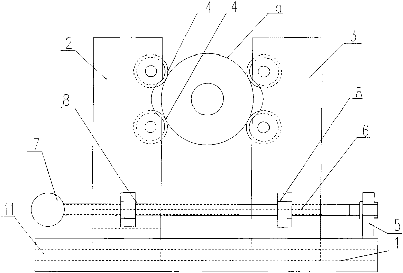
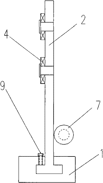
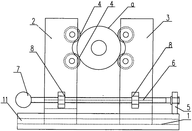
[0018] see figure 1 , figure 2 , the present invention is used for the clamping device of plate roll processing, comprises base 1, left moving vertical board 2, right moving vertical board 3, four rollers 4, by bracket 5, screw mandrel 6, hand wheel 7 and two nuts 8 Composed screw drive mechanism and two locking screws 9.

[0019] A chute 11 extending left and right is provided in the base 1 .

[0020] The left mobile vertical plate 2 and the right mobile vertical plate 3 are respectively installed on the left and right sides of the base and can move left and right along the chute 11.

[0021] Four rollers 4 are symmetrically installed on the opposite sides of the left mobile vertical plate 2 and the right mobile vertical plate 3, and the center formed by the four rollers is consistent with the center of the lathe. Four rollers among the present invention adopt the same size bearing.

[0022] The bracket 5 is fixed on the right end of the base 1.

[0023] Two nuts 8 are ...


PUM


Abstract

The invention provides a clamping device for a processing roller, which comprises a base, a left moveable upright plate, a right moveable upright plate, four idler wheels, two locking bolts and a screw rod transmission mechanism formed by a bracket, a screw rod, a hand wheel and two nuts. The center formed by the four idler wheels is corresponding to the center of a lathe. The clamping device of the invention has a self-positioning function, is capable of rapidly clamping and releasing a workpiece and is convenient to disassemble the workpiece.

Description

technical field [0001] The invention relates to an equipment processing tool, in particular to a clamping device for plate roll processing. Background technique [0002] At present, the clamping device used for the processing of the plate roller on the lathe is a three-point positioning center frame, and the adjustment of each fulcrum is adjusted separately. There is a problem of inconvenient adjustment. High technical requirements for employees. Contents of the invention [0003] The object of the present invention is to provide a clamping device for plate roll processing in order to solve the above problems. [0004] In order to achieve the above object, the present invention adopts the following technical solutions: a clamping device for plate roll processing, which is installed on a lathe for clamping plate rolls, which includes: [0005] The base is provided with a chute extending left and right; [0006] The left moving vertical plate and the right moving vertica...

Claims


Application Information

Patent Timeline
Patent Type & Authority Patents(China)
IPC IPC(8): B23Q3/06
Inventor 姚根龙
Owner SHANGHAI YUNAN PLATE MAKING
Learn More