Intelligent cyclic loading test device for shear-resistant part
A technology of cyclic loading and testing equipment, which is applied in the direction of measuring equipment, using stable shear force to test the strength of materials, instruments, etc., can solve the problems of single function and difficulty in simulating the real stress situation in the test of shear parts, and achieve Multiple functions, improved efficiency and accuracy, and stable structure
- Summary
- Abstract
- Description
- Claims
- Application Information
AI Technical Summary
Problems solved by technology
Method used
Image
Examples
Embodiment 1
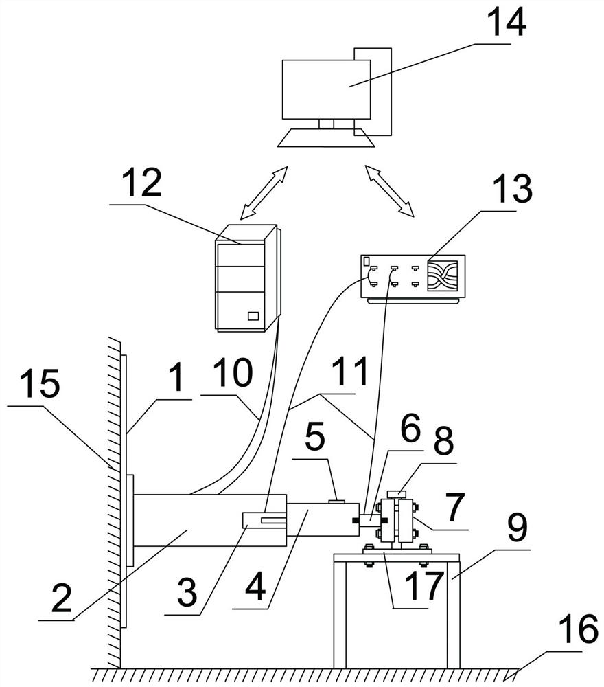
[0027] Embodiment 1: This embodiment aims to provide an intelligent test device for cyclic loading of shear parts. In view of the shortcomings of the existing structure, it is impossible to truly simulate the actual force condition of the shear parts. This embodiment can not only easily realize one-way loading Shear testing, but also cyclic loading smart shear testing can be easily implemented as required.
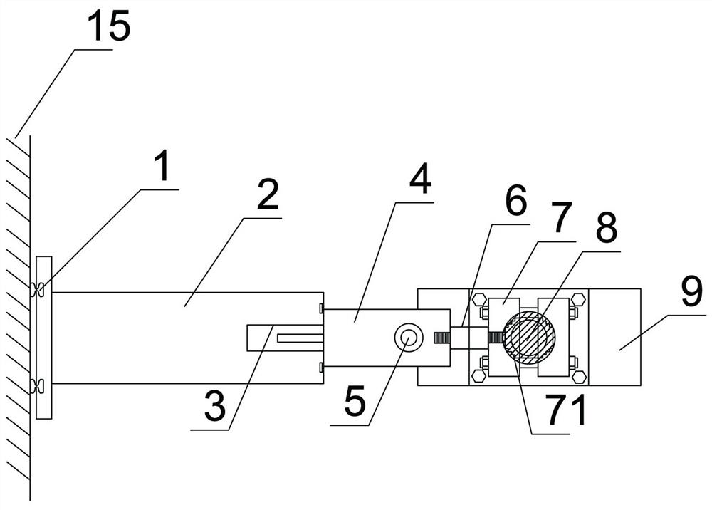
[0028] like figure 1 As shown, an intelligent test device for cyclic loading of shear parts includes a vertical fixed plate, an actuator, a fixture and a test platform; the vertical fixed plate is vertically fixed on the shear wall, and the vertical fixed plate The middle part is vertically provided with double track 1 arranged at intervals, and the bottom of the actuator 2 is provided with a track groove corresponding to the double track 1, and the track is in a dovetail structure, so that the bottom of the actuator 2 is nested on the track. The double dovetail-shaped ra...
Embodiment 2
[0032] Embodiment 2: This embodiment is basically the same as Embodiment 1, the difference is that this embodiment further limits the structure of the clamp.
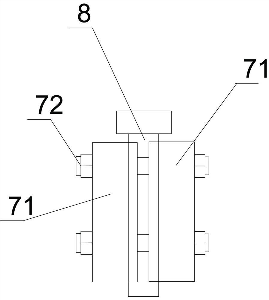
[0033] Fixture 7 comprises two halves 71 and connecting bolts 72, the butt joint surfaces of two halves 71 have corresponding notches 73, the four corners of two halves 71 are provided with corresponding through holes, and the connecting bolts are set in the through holes so that the two halves The half pieces are connected together, the side wall of the notch is provided with fine teeth, the clamp 7 is clamped on the shearing part, and the fixing fixture can make the shearing part firmly fixed, and the radian of the notch 73 is smaller than π at the same time. Different clamps can be used for shear parts of different specifications. During the clamping process, the fine teeth include tooth blocks connected together. The tooth blocks are basically in the shape of an isosceles triangle. Shaped parts, and the shear parts ...
Embodiment 3
[0034] Embodiment 3: This embodiment is basically the same as Embodiment 1, the difference is that this embodiment further limits the installation method of the load sensor.
[0035] Both sides of the load sensor 6 are provided with screw rods, and the thread directions of the screw rods on both sides are opposite. The middle part of the clamp 7 and the middle part of the telescopic rod 4 are provided with corresponding screw holes. The screw rods are synchronously connected on the telescopic rod 4 and the clamp 7.
[0036] Simultaneously in this embodiment, because screw hole is respectively arranged in the middle part of telescopic rod 4 and clamp 7, thereby when completing connection, screw hole and screw rod have certain rigidity, thereby makes the middle part of clamp and telescopic rod 4 correspond to the middle part, and The middle part of the fixture is provided with a notch correspondingly, and the middle part of the shear member can be made to correspond to the middl...
PUM
 Abstract
Description
Claims
Application Information
 - R&D
- Intellectual Property
- Life Sciences
- Materials
- Tech Scout
- Unparalleled Data Quality
- Higher Quality Content
- 60% Fewer Hallucinations
Browse by: Latest US Patents, China's latest patents, Technical Efficacy Thesaurus, Application Domain, Technology Topic, Popular Technical Reports.
© 2025 PatSnap. All rights reserved.Legal|Privacy policy|Modern Slavery Act Transparency Statement|Sitemap|About US| Contact US: help@patsnap.com


