Compensating device for elevator

A compensation device and elevator technology, applied in the field of elevator parts, can solve problems such as safety concerns, device damage, failure to protect the safety brake of the guide device, etc., and achieve the effects of uniform force strength, convenient weight, and space saving in the pit of the shaft

Active Publication Date: 2010-12-22
CANNY ELEVATOR
View PDF6 Cites 11 Cited by
  • Summary
  • Abstract
  • Description
  • Claims
  • Application Information

AI Technical Summary

Problems solved by technology

The compensation device of the elevator with this structure does not have a safety device. When the elevator compensation rope jumps too much, it cannot protect the guide device with the required weight to brake safely, resulting in damage to the entire device, which poses safety concerns.

Method used


Image

  • Compensating device for elevator
  • Compensating device for elevator
  • Compensating device for elevator

Examples


Embodiment Construction

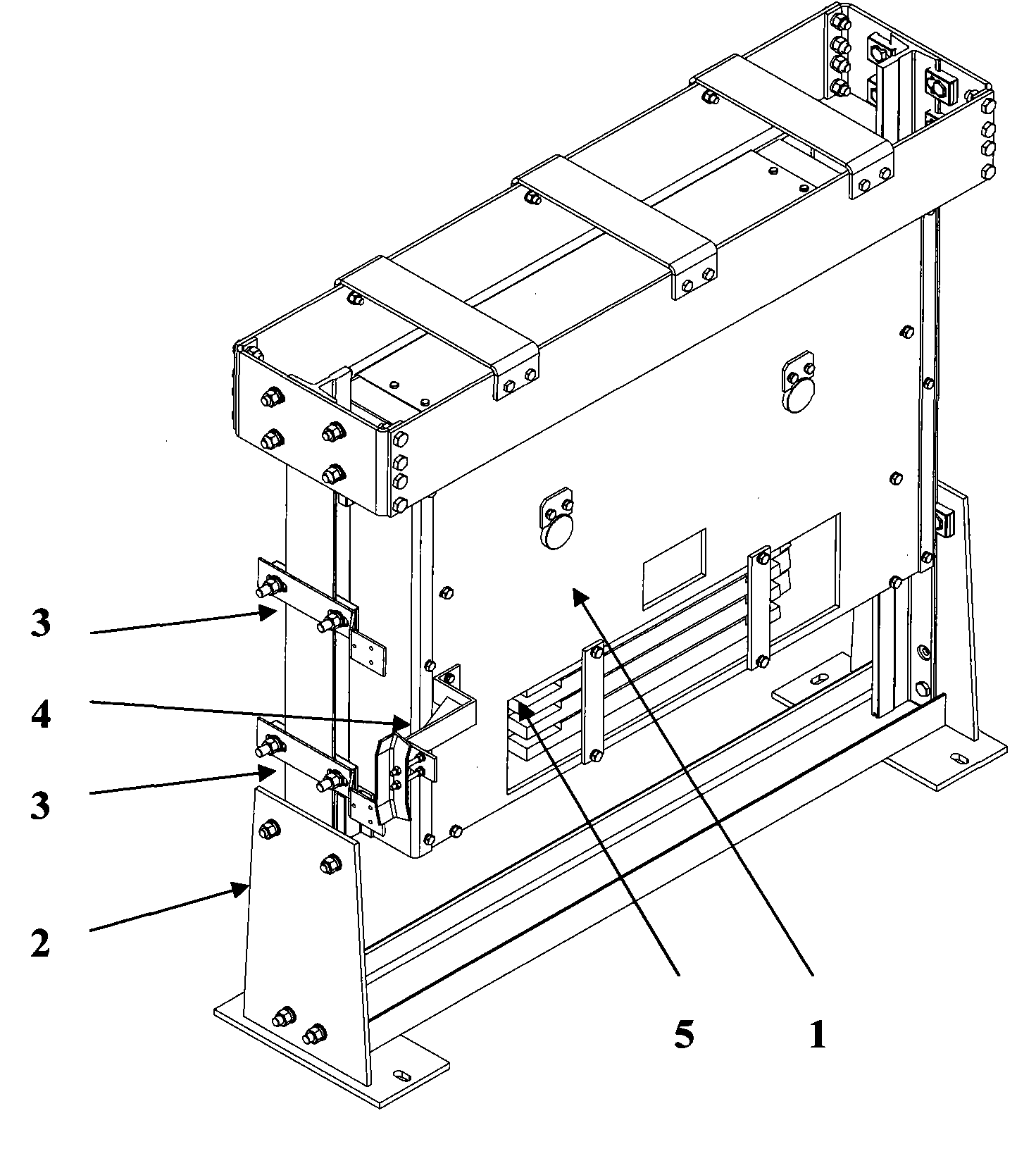
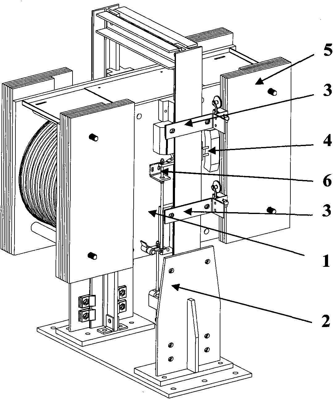
[0016] Such as figure 2 and image 3 As shown, a compensating device for an elevator of the present invention includes a guide device 1 , a fixing device 2 , a travel switch frame 3 , a limit ram frame 4 , a counterweight block 5 and a safety device 6 . Both ends of the fixing device 2 are vertical guide rails. The guiding device 1 is slidingly connected with the guide rails at both ends of the fixing device 2 . The two ends of the guide device 1 are respectively connected with the compensation ropes on the car and the counterweight. The compensation rope traction guide device 1 moves up and down along the guide rail of the fixing device 2 . Travel switch frame 3 has four. Two travel switch frames 3 are respectively arranged up and down in each guide rail of the fixing device 2 . The travel switch frame 3 can be adjusted up and down along the guide rail of the fixing device 2 . The limit stroke frame 4 is installed on the guide device 1 and is located between the travel...


PUM


Abstract

The invention relates to a compensating device for an elevator. The compensating device comprises a guiding device, a fixing device, a stroke switch frame, a limit bow striking frame, a clump weight and a safety device, wherein the safety device comprises safety tongs, a lifting rod, a linkage device, a pull rod and a positioning plate; two safety tongs are fixedly connected at the two ends of the guiding device respectively; the lower end of each safety tongs is fixedly connected with the upper end of the lifting rod; the lower end of the lifting rod is connected with the linkage device; the linkage device penetrates into a reserved hole of the guiding device and can radially rotate; the upper end of the pull rod is connected with the linkage device, and the lower end of the pull rod penetrates into the hole of the positioning plate; and the positioning plate is fixed on the fixing device. In the technical scheme of the invention, when the guiding device moves upwards, the pull rod can move upwards with the guiding device, and after the pull rod moves for a certain distance, the safety tongs can act, so that the guiding device brakes on the fixing device timely and is prevented from rushing out of the fixing device.

Description

technical field [0001] The invention relates to an elevator component, in particular to an elevator compensation device. Background technique [0002] Such as figure 1 As shown, the commonly used elevator compensation device includes five parts: guide device, fixing device, travel switch frame, limit impact bracket and counterweight block. Both ends of the fixing device are vertical guide rails. The guiding device is slidingly connected with the guide rails at both ends of the fixing device, and the two tensioning wheels in the guiding device and the fixing device are in the same plane. The two ends of the guiding device are respectively connected with the car and the compensation rope on the counterweight. The compensation rope traction guide moves up and down along the guide rail of the fixing device. There are four travel switch frames. Two travel switch frames are respectively arranged up and down in each guide rail of the fixing device. The limit switch frame can ...

Claims


Application Information

Patent Timeline
Patent Type & Authority Applications(China)
IPC IPC(8): B66B7/00B66B5/02
CPCB66B7/068
Inventor 张建宏俞诚郑尧
Owner CANNY ELEVATOR
Why Eureka
Try Eureka