Circuit emulation over ip interworking vll

一种电路仿真、IP地址的技术,应用在通过路径配置进行数据交换、电气元件、网络互连等方向,能够解决不能够提供电路仿真等问题

Inactive Publication Date: 2010-12-22
ALCATEL LUCENT SAS
View PDF4 Cites 0 Cited by
  • Summary
  • Abstract
  • Description
  • Claims
  • Application Information

AI Technical Summary

Problems solved by technology

[0006] Typical implementations of the above technologies are not capable of providing IP / UDP based circuit emulation over MPLS networks when one endpoint is Ethernet and the other is a non-Ethernet technology (CEM)

Method used


Image

  • Circuit emulation over ip interworking vll
  • Circuit emulation over ip interworking vll
  • Circuit emulation over ip interworking vll

Examples


Embodiment Construction

[0024] Referring now to the drawings, in which like numerals indicate like components or steps, there are disclosed broad aspects of various illustrative embodiments.

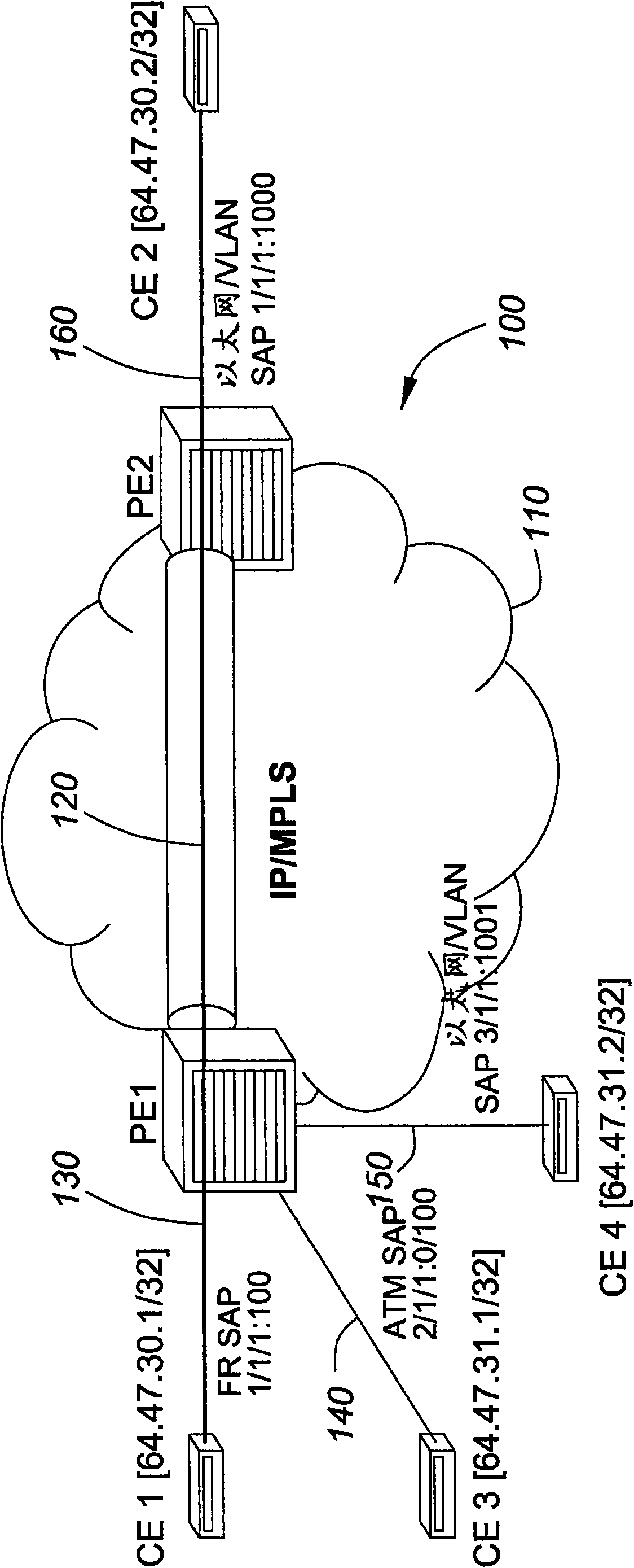
[0025] figure 1 is a schematic diagram of an embodiment of an exemplary system 100 for IP interworking VLLs. System 100 includes IP / MPLS network cloud 110, CE1, CE2, CE3, CE4, PE1 and PE2. CE1 is represented by the IP address 64.47.30.1 / 32. CE2 is represented by the IP address 64.47.30.2 / 32. CE3 is represented by the IP address 64.47.31.1 / 32. CE4 is represented by IP address 64.47.31.2 / 32.

[0026] CE1 is connected to PE1 through communication line 130 . In the system 100 shown, the communication line 130 is indicated as FR SAP 1 / 1 / 1:100. CE 2 is connected to PE 2 through communication line 160 . In system 100, communication line 160 is depicted as Ethernet / VLAN SAP 1 / 1 / 1:1000. CE3 is connected to PE1 through communication line 140 described as ATM SAP 2 / 1 / 1:0 / 100. CE4 is connected to PE1 through commu...


PUM


Abstract

A method of circuit emulation over an IP interworking VLL, and related system, the method including one or more of the following: configuring a circuit emulation port with one or more logical interfaces; configuring one or more channels on each of the one or more logical interfaces; configuring the one or more channels with a destination IP address; configuring the one or more channels with a destination UDP port number; specifying an Ipipe VLL for each of the one or more channels; determining TDM traffic to go onto the specified Ipipe; packetizing TDM traffic; encapsulating the TDM traffic with encapsulation; inserting one or more packets of the TDM traffic into an IP interworking VLL; sending the one or more packets through the Ipipe; stripping the encapsulation from the one or more packets of the TDM traffic; and forwarding the one or more packets to a destination.

Description

technical field [0001] The present invention generally relates to circuit emulation in networks. Background technique [0002] Virtual Leased Line (VLL) is a means of providing Ethernet-based point-to-point communications over Internet Protocol (IP) and Multiprotocol Label Switching (MPLS) networks (IP / MPLS). This technology is also sometimes referred to as Virtual Private Wire Service (VPWS) or Ethernet over MPLS (EoMPLS). VLL typically uses pseudowire encapsulation to tunnel Ethernet traffic through MPLS over an IP / MPLS backbone. [0003] In computer networking and communications, MPLS is a data-carrying mechanism that belongs to the family of packet-switched networks. MPLS works at the layers of the OSI model, which are generally considered to lie between the traditional definition of layer 2, or the data link layer, and layer 3, or the network layer. Therefore, MPLS may also be referred to as a "layer 2.5" protocol. [0004] MPLS was designed to provide a unified dat...

Claims


Application Information

Patent Timeline
Patent Type & Authority Applications(China)
IPC IPC(8): H04L12/46
CPCH04L12/4633H04L12/2852
Inventor S·皮尔布哈尔N·哈特
Owner ALCATEL LUCENT SAS
Why Eureka
Try Eureka