Dust-removing device for inkjet printer
A technology of inkjet printers and dust removal devices, which is applied in printing devices, printing, etc., and can solve problems such as abnormal sensing functions
Inactive Publication Date: 2010-12-29
KINPO ELECTRONICS
0 Cites 7 Cited by
AI-Extracted Technical Summary
Problems solved by technology
[0003] In the case of inkjet printers, ink aerosols will be generated during inkjet, and ink aerosols will randomly adhere to the interior of the printer, including the surface of the internal printed circuit board semi-finished product (Printed Circuit Board Assembly abbre...
Method used
[0043] The second inner side 221 is provided with a cloth friction member 212 to rub against the elongated plastic part 170 to generate static electricity. Similarly, the first inner side 211 can also be provided with a cloth friction member 212 to increase the friction device 210 The contact area with the strip-shaped plastic part 170 is to enhance the effect of static electricity. It is worth noting that the shape and material of the cloth friction member 212 are not limited, as long as it can rub against the elongated plastic member 170 to generate static electricity, cloth or paper materials are preferred, but not limited . In addition, the cloth friction member 212 may also be disposed on the back of the bearing seat 120 at a position corresponding to the friction device 210 to increase the contact area between the cloth friction member 212 and the elongated plastic member 170 . In addition, in order to enhance the friction effect between the cloth friction member 212 and the elongated plastic member 170 , patterns may also be provided on the cloth friction member 212 to increase the effect of static electricity. In this embodiment, in order to increase the friction area between the friction device 210 and the elongated plastic part 170, the height D1 (shown in FIG. 2B ) formed by the second inner surface 221 is equal to or gre...
Abstract
The invention discloses a dust-removing device for an inkjet printer, which comprises a strip plastic part and a friction device, wherein, the strip plastic part is fixedly arranged in a shell of the printer; and the friction device is provided with a cloth friction piece and arranged on a bearing seat in the printer. While the bearing seat is moved, the friction device moves along with the bearing seat and meanwhile the cloth friction piece and the strip plastic part rub against each other to generate static electricity for adsorbing ink aerosol generated by an inkjet head. Therefore, the dust-removing device can avoid the ink aerosol being adhered on a sensing element to affect normal operation of the printer.
Application Domain
Other printing apparatus
Technology Topic
EngineeringInkjet printing +3
Image
Examples
- Experimental program(2)
Example
[0038] First embodiment
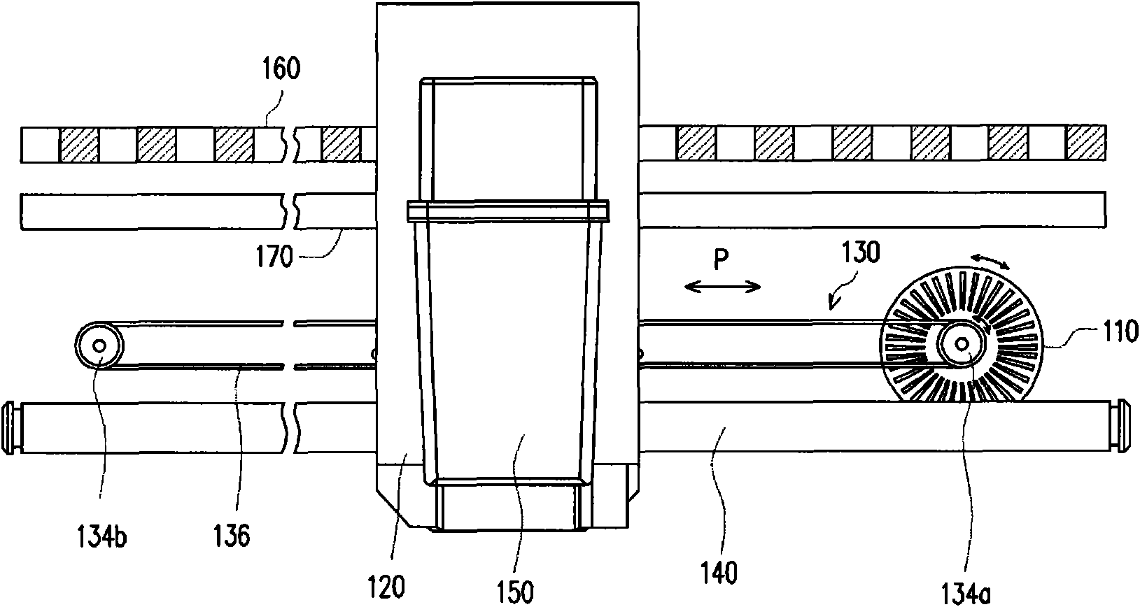
[0039] Please refer to figure 1 , figure 1 It is a schematic diagram of a part of the internal structure of a printer according to an embodiment of the present invention. The printer includes a transmission mechanism 130, a shaft 140, a bearing base 120, an optical ruler 160, and a long plastic member 170. The supporting base 120 is slidably disposed on the guide rod 140, and the transmission mechanism 130 is connected to the supporting base 120 and used to drive the supporting base 120 to move along a path P. The ink clip 150 is detachably disposed on the supporting base 120 and can be used for printing along with the movement of the supporting base 120. The transmission mechanism 130 includes a stepping motor 110, a pulley 134a, a driven wheel 134b, and a belt 136. The stepping motor 110 is used to drive the pulley 134a to rotate to drive the belt 136, and the bearing seat 120 is connected to the belt 136 and is received by the belt 136. , And move along the path P.
[0040] The optical ruler 160 is fixed on the casing (not shown) of the printer and is arranged behind the bearing base 120. The optical ruler 160 is a plastic sheet with interlaced light-transmitting and opaque gratings, and is matched with an optical encoder (encoder). ) In response to the optical scale 160, a positioning signal can be provided to locate the position of the carrier 120. The elongated plastic member 170 is fixed to the casing of the printer, behind the supporting base 120 and under the optical ruler 160.
[0041] A friction device (not shown) is provided on one side of the carrier 120 (the side close to the elongated plastic member 170). The friction device has a cloth friction member to contact the elongated plastic member 170. The friction device will follow the load The movement of the seat 120 rubs the elongated plastic member 170 with the cloth friction member, so that the elongated plastic member 170 generates static electricity to absorb ink aerosol. When the carrier 120 moves along the path P, the friction device behind the carrier 120 interacts with the elongated plastic member 170 to generate static electricity, and then absorbs the ink aerosol and is adsorbed on the ink float of the elongated plastic member 170. The quality can be brushed to the two sides of the elongated plastic member 170 by the movement of the friction device to prevent ink aerosol from being adsorbed on the optical scale 160 or the sensing element of the optical encoder.
[0042] It is worth noting that the setting position of the friction device please refer to Figure 2A , Figure 2A It is a schematic diagram of the structure of the friction device and the bearing seat according to the first embodiment of the present invention, wherein the friction device 210 is clamped on the bearing seat 120 and has an open accommodating portion 215 for disposing the elongated plastic member 170, the accommodating portion 215 A cloth friction member 212 is provided on an inner side wall of the ”to contact the elongated plastic member 170; the cloth friction member 212 can rub against the elongated plastic member 170 to generate static electricity when the carrier 120 moves. In this embodiment, please refer to the structure of the friction device 210 Figure 2B , Figure 2B It is a schematic structural diagram of the friction device 210 according to the first embodiment of the present invention. The friction device 210 has a buckle part 316 for being clamped on the carrier 120. The friction device 210 has a top 206 and a first side wall 202. The top 206 has a first inner side 211, and the first side wall 202 has a second inner side 221 to form a receiving portion 215. The elongated plastic member 170 can be inserted into the receiving portion 215 of the friction device 210 and bears against the second inner surface 221 of the friction device 210.
[0043] The second inner side 221 is provided with a cloth friction member 212 to rub against the elongated plastic member 170 to generate static electricity. Similarly, the first inner side 211 can also be provided with a cloth friction member 212 to increase the friction device 210 and the elongated plastic member 170. The contact area of the shaped plastic part 170 is to enhance the effect of static electricity. It is worth noting that the shape and material of the cloth friction member 212 are not limited, as long as the material can be rubbed with the long plastic member 170 to generate static electricity. Among them, cloth or paper materials are preferred, but not limited. . In addition, the cloth friction member 212 can also be arranged at a position on the back of the carrier 120 corresponding to the friction device 210 to increase the contact area between the cloth friction member 212 and the elongated plastic member 170. In addition, in order to enhance the friction effect between the cloth friction member 212 and the elongated plastic member 170, the cloth friction member 212 may also be provided with patterns to increase the effect of generating static electricity. In this embodiment, in order to increase the friction area between the friction device 210 and the elongated plastic member 170, the height D1 formed by the second inner side surface 221 ( Figure 2B Shown) is equal to or greater than the height D2 of the elongated friction member 170 (e.g. Figure 2A Shown).
[0044] In addition, the friction device 210 and the bearing seat 120 can be connected in a snap-fit manner. The main function of the snap portion 316 is to connect the friction device 210 and the bearing seat 120. The structure can be a hook or a tenon connection structure, as long as The supporting base 120 is provided with a corresponding locking structure, such as a card slot, which can be correspondingly locked, which is not limited in this embodiment. In addition, the connection method between the friction device 210 and the bearing seat 120 can also be connected by means of devil felt bonding, screw locking, bonding or button fastening, which is not limited in this embodiment.
[0045] It is worth noting that the structure of the friction device 210 is not limited to Figure 2B As shown, as long as the long plastic part 170 can be inserted through it, and the long plastic part 170 can be rubbed when the carrier 120 moves to generate static electricity. The material of the cloth friction parts 212, 214 can be capillary material or the capillary material of the devil felt, as long as the material value can generate static electricity by friction with the long plastic part 170, and this embodiment is not limited. In addition, the shape of the elongated plastic member 170 can also be a sheet shape, which can increase the surface area for friction to increase the effect of generating static electricity.
Example
[0046] Second embodiment
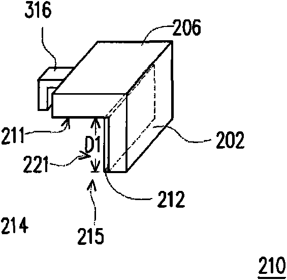
[0047] The friction device of the present invention is not limited to the above Figure 2B The inverted L shape in the middle can also be implemented with an opening structure such as a U shape, a semicircle, etc. Please refer to Figure 3A versus Figure 3B , Figure 3A It is a schematic diagram of the structure of the friction device and the bearing base according to the second embodiment of the present invention, in which the friction device 310 is in the shape of a "". Figure 3B It is a schematic diagram of the structure of the friction device according to the second embodiment of the present invention. Figure 3B The middle depicts a friction device 310 in the shape of a "". The friction device 310 has a first side wall portion 202, a second side wall portion 204 and a top 206, and forms a receiving portion 215 in the shape of a "". The main difference between the friction device 310 and the friction device 210 lies in the second side wall portion 204, and the inner side surfaces 221 and 231 of the first side wall portion 202 and the second side wall portion 204 of the friction device 310 can be provided with cloth friction members respectively 212, 214. In addition, the inner surface 211 of the top 206 of the receiving portion 215 may also be provided with a cloth friction member to increase the contact area between the friction device 310 and the elongated plastic member 170. It should be noted that the cloth friction member can be selectively disposed on any inner side surface of the receiving portion 215, and this embodiment is not limited.
[0048] It is worth noting that the structure of the friction device is not limited to Figure 2A~Figure 3B As shown, as long as it has an opening structure, the long plastic part 470 can be inserted through it, and the long plastic part 470 can be rubbed when the carrier 120 moves to generate static electricity. The shape of the receiving parts 215, 315 is not limited to the above Figure 2A~Figure 3B As shown, it can be any opening shape, as long as the elongated plastic member 170 can be fitted into it and bear against the inner surface of the friction device 210, 310. The opening of the friction device is not limited to downward or upward, as long as it is sufficient to provide the elongated plastic member 170. This embodiment does not limit the shape and opening direction of the receiving portions 215 and 315. The material of the cloth friction member 412 can be a capillary material or a capillary material in the devil's felt, as long as it can rub against the elongated plastic member 170 to generate static electricity, and this embodiment is not limited. In addition, the shape of the elongated plastic part 470 can also be a sheet shape, which can increase the surface area for friction to increase the effect of generating static electricity.
[0049] Next, please refer to figure 1 , Figure 2A versus Figure 4 , Figure 4 It is a schematic diagram of an inkjet printer according to an embodiment of the present invention, in which the elongated plastic member 170 is disposed under the optical ruler 160. When the carrier 120 moves, the elongated plastic member 170 is rubbed to generate static electricity to absorb ink float. quality. In addition, during the movement of the carrier 120, the cloth friction member 212 in the friction device 210 pushes the ink aerosol absorbed by the long plastic member 170 to the two ends of the long plastic member 170. The vibration caused by the inkjet printer when the bearing base 120 is driven will cause the ink aerosol that has been pushed to the ends of the long plastic member 170 to fall into the collection area or collection device to prevent the ink aerosol from affecting the inkjet printer. Electronic or optical parts cause malfunction. Wherein, the collecting device can be arranged under the two ends of the elongated plastic member 170, or a collecting area can be formed in the housing of the inkjet printer to collect the dropped ink aerosol.
[0050] The elongated plastic part 170 is arranged according to the original inkjet printer structure and the transmission structure of the carrier 120, and will not affect the original transmission mode of the carrier 120, and there is no need to add a new transmission mechanism. The present invention utilizes the elongated plastic member 170 and the friction device 210 provided on the back of the bearing seat 120 to achieve the effect of eliminating ink aerosol at the same time when the inkjet printer performs printing.
[0051] To sum up, the present invention adds a long plastic part and a friction device to the inkjet printer. When the carrier is moved, the friction device will be driven to rub the long plastic part to generate static electricity, and then absorb ink aerosol. In this way, the ink aerosol can be prevented from being adsorbed on electronic components such as optical scales or optical sensors and affecting the normal operation of the inkjet printer.
PUM


Description & Claims & Application Information
We can also present the details of the Description, Claims and Application information to help users get a comprehensive understanding of the technical details of the patent, such as background art, summary of invention, brief description of drawings, description of embodiments, and other original content. On the other hand, users can also determine the specific scope of protection of the technology through the list of claims; as well as understand the changes in the life cycle of the technology with the presentation of the patent timeline. Login to view more.