Light source unit and illumination device

A technology of a light source unit and a lighting device, which is applied in the direction of lighting devices, components of lighting devices, light sources, etc.

Inactive Publication Date: 2010-12-29
KK TOSHIBA +1
View PDF7 Cites 2 Cited by
  • Summary
  • Abstract
  • Description
  • Claims
  • Application Information

AI Technical Summary

Problems solved by technology

[0013] The object of the present invention is to overcome the defects of the existing light source unit and lighting device, and provide a light source unit and lighting device with a new structure. The technical problem to be solved is to prevent the It can

Method used


Image

  • Light source unit and illumination device
  • Light source unit and illumination device
  • Light source unit and illumination device

Examples


Embodiment Construction

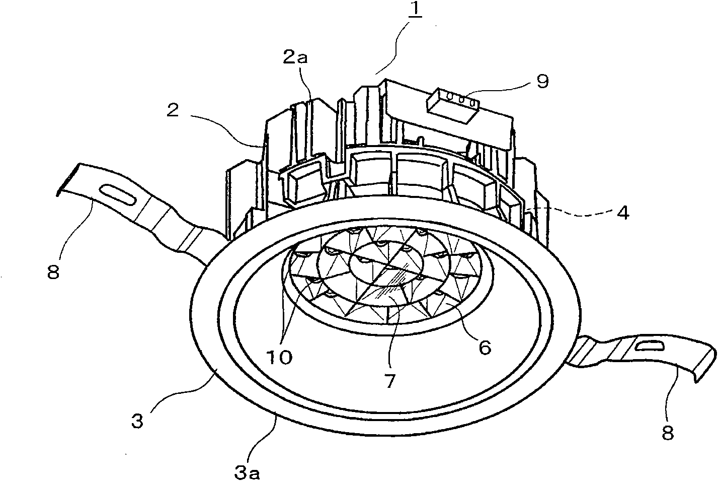
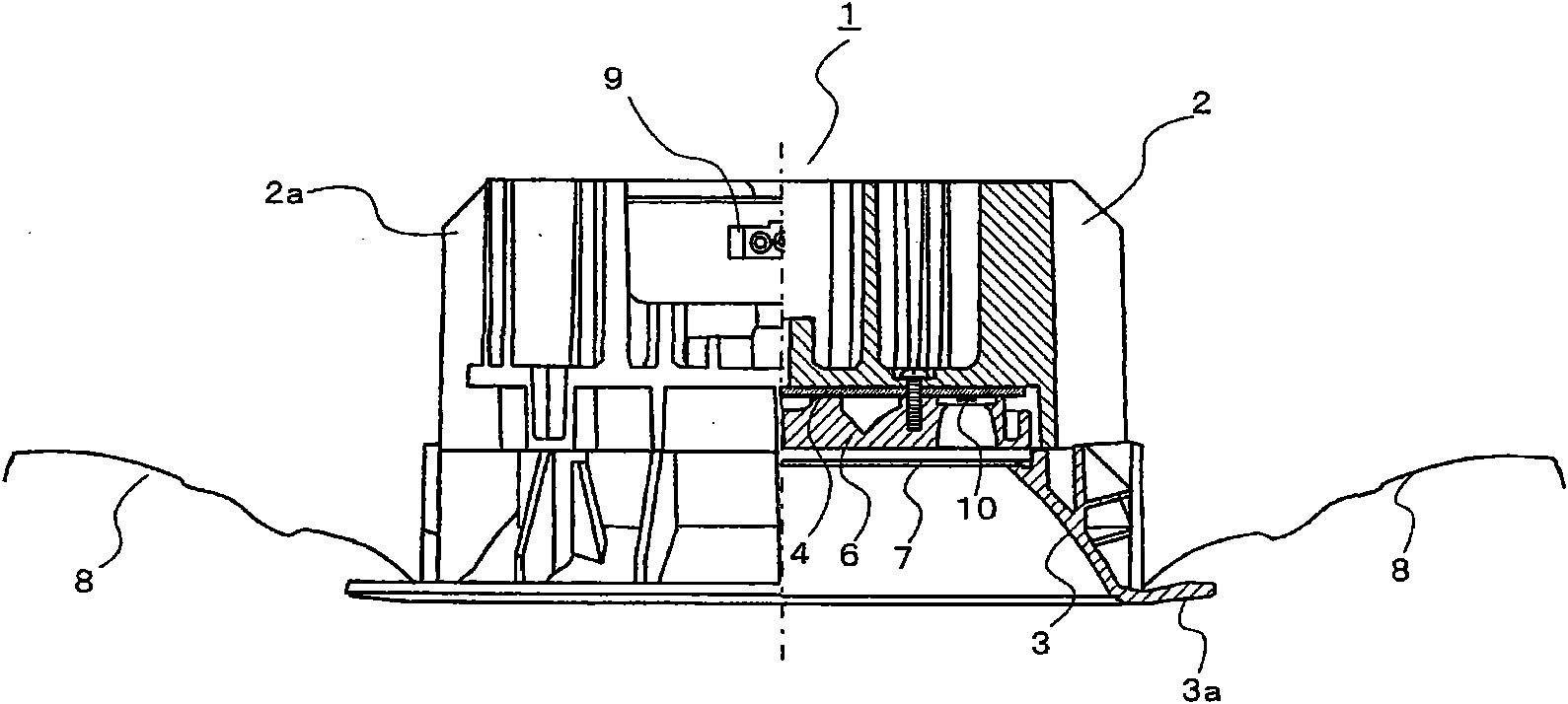
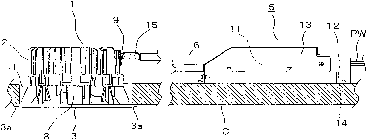
[0052] In order to further explain the technical means and effects that the present invention adopts to achieve the intended purpose of the invention, the specific implementation, structure, characteristics and features of the light source unit and lighting device proposed according to the present invention will be described below in conjunction with the accompanying drawings and preferred embodiments. Efficacy, detailed as follows.

[0053] A light source unit of one example includes a substrate on which a plurality of light emitting elements are mounted, a plurality of incident openings respectively corresponding to the plurality of light emitting elements, an exit opening through which light passing through the incident openings is emitted, and an expansion port extending from the entrance openings to the exit openings. A plurality of open reflective surfaces, among the plurality of reflective surfaces, the reflective surfaces located on the outermost side are arranged to be...


PUM


Abstract

The invention relates to a light source unit and an illumination device. The light source unit includes a substrate and a reflective body. The substrate includes a plurality of light-emitting elements mounted thereon. The reflective body includes a plurality of incident openings each corresponding to one of the plurality of light-emitting elements, an output opening to which light that has passed through the incident opening is output, and a plurality of reflective surfaces that expand from the incident opening toward the output opening. Reflective surfaces included in the plurality of reflective surfaces and positioned on an outermost side are provided to be adjacent to one another, and an angle is set so as to prevent reflective light of light emitted from the light-emitting elements from traveling toward an outer side in a reflective surface formed on the outer side. The invention also provides the illumination device using the light source unit.

Description

technical field [0001] The present invention relates to a light source unit (unit) using a light emitting element such as a light emitting diode (Light Emitting Diode, LED), and a lighting device using the light source unit. Background technique [0002] In recent years, lighting devices in which a light emitting element such as an LED is mounted on a substrate and the light emitting element is used as a light source have been developed. For example, the lighting device is as Figure 8 Shown is a down light recessed into the ceiling. First, the outline of the downlight 101 will be described. [0003] The downlight 101 includes a thermally conductive cylindrical body 102, a decorative frame 103 mounted on the cylindrical body 102, a substrate 104 also mounted on the cylindrical body 102 and equipped with an LED 110 as a light emitting element, and housed in the cylindrical body 102. A power supply unit 105 , a reflector 106 , and a translucent cover 107 disposed in front of...

Claims


Application Information

Patent Timeline
IPC IPC(8): F21S2/00F21V7/00
CPCF21K9/00F21Y2101/02F21Y2115/10F21K9/68
Inventor 樋口一斎森山厳与桥本纯男神代真一
Owner KK TOSHIBA
Why Eureka
Try Eureka