Length-adjustable shaft

A technology for adjusting shafts and shaft parts, which is applied in the field of adjustable length shafts

Inactive Publication Date: 2010-12-29
VOITH PATENT GMBH
View PDF1 Cites 8 Cited by
  • Summary
  • Abstract
  • Description
  • Claims
  • Application Information

AI Technical Summary

Problems solved by technology

[0005] One problem is that lubricant will deposit in

Method used


Image

  • Length-adjustable shaft
  • Length-adjustable shaft
  • Length-adjustable shaft

Examples


Embodiment Construction

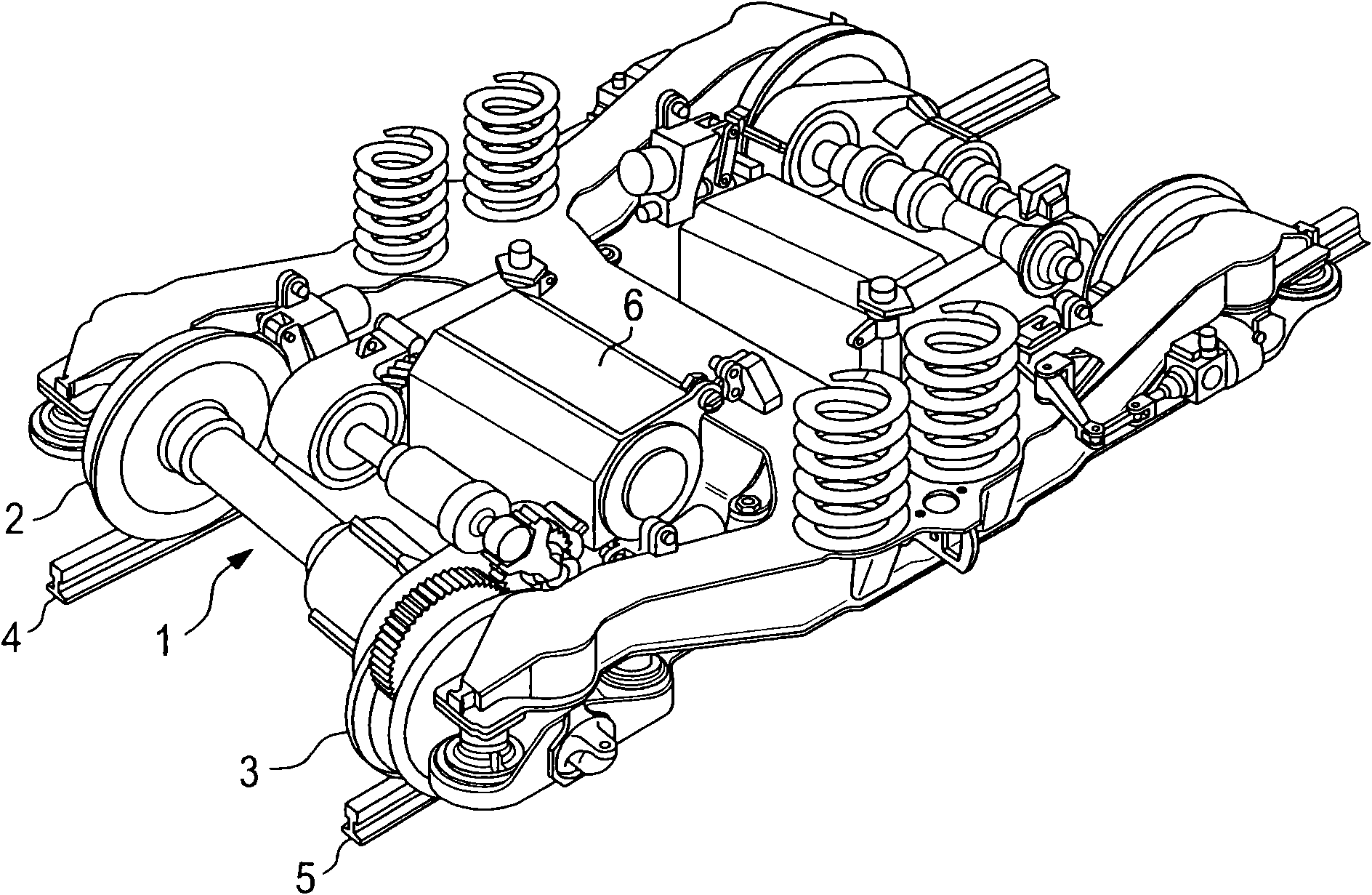
[0019] for such as figure 1 The wheel set of the rail vehicle shown in includes two axles, of which only axle 1 is discussed here. The length of shaft 1 is adjustable. The shaft supports the wheels 2, 3 at its two ends respectively. Wheel can roll on guide rail 4,5.

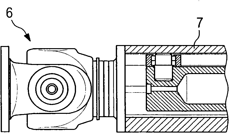
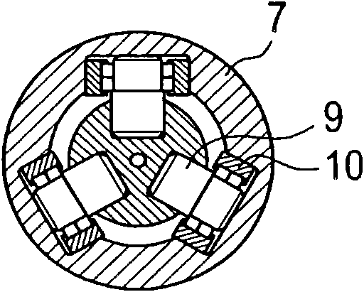
[0020] A universal joint 6 is arranged in front of each wheel 2,3. The shaft 1 comprises an outer shaft part 7 and an inner shaft part 8 . The shaft portion 7 is sleeve-shaped. It rests on the inner shaft part 8 via three bearings. image 3 Three bearings (tripod) are shown in cutaway view. The inner shaft portion 8 comprises a blind hole. A bearing pin 9 is embedded in each blind hole. It supports the roller bearing 10 . Roller bearings 10 engage in longitudinal grooves of the outer shaft portion 7 .

[0021] The three roller bearings 10 thus roll in the longitudinal grooves during the telescopic movement of the outer shaft part 7 and the inner shaft part 8 .

[0022] Figure 4 The configuration of t...


PUM


Abstract

The invention relates to a length-adjustable shaft comprising - an outer sleeve-shaped axial part; - an inner axial part which can be pushed into and deployed out of the outer axial part in a telescopic fashion and which encloses a buffer chamber; - having a bearing which is arranged between the two axial parts and which can be lubricated with a lubricant; - that end of the inner axial part which can be pushed into the outer axial part has an end wall; - a ventilation opening is provided which connects, in a conducting fashion, the buffer chamber to the cavity which is enclosed by the outer axial part. The invention is characterized by the following features: the ventilation opening comprises at least one bore which is offset with respect to the rotational axis of the shaft.

Description

technical field [0001] The invention relates to an adjustable-length shaft comprising an outer shaft portion and an inner shaft portion cooperating with each other in a telescopic manner. This type of shaft is a cardan shaft used in rolling mills to drive the rolls. Such axles are also used in the construction of vehicles, for example in the wheelsets of rail vehicles (see SE 0702642). The present invention is based on this prior art. Background technique [0002] The shaft consists of two parts, an outer sleeve-like shaft portion and an inner shaft portion. The inner shaft portion telescopically moves within the outer shaft portion in a limited manner. The length of the overall shaft can thus vary within certain limits. [0003] A bearing is provided between the two shaft parts. It may comprise, for example, three or more roller bearings. The bearings are arranged with their longitudinal axes perpendicular to the axis of rotation of the roller. Each bearing is suppor...

Claims


Application Information

Patent Timeline
IPC IPC(8): B61C9/26B61C9/52
CPCF16D3/2055F16D3/06B61C9/52F16C3/03B61F3/04F16D2300/06F16C2326/10F16D2300/0212B61C9/26B61F17/00
Inventor F·斯塔巴蒂H·里希特
Owner VOITH PATENT GMBH
Why Eureka
Try Eureka