Eureka AIR delivers breakthrough ideas for toughest innovation challenges, trusted by R&D personnel around the world.

Self-weighing hopper of loading and unloading device

A technology for loading and unloading equipment and hoppers, applied in the directions of loading/unloading, packaging, transportation and packaging, which can solve the problems of large impact on load-bearing conveying equipment, affecting production efficiency, high failure frequency and maintenance frequency, etc., and achieve effective vibration and blockage. , to ensure the effect of continuity and high efficiency

Inactive Publication Date: 2011-01-05
无锡工力工程机械厂
View PDF0 Cites 8 Cited by
  • Summary
  • Abstract
  • Description
  • Claims
  • Application Information

AI Technical Summary

Problems solved by technology

The traditional single-side movable hopper door cannot meet the working conditions required for materials with poor fluidity. The sliding plate hopper door is not only difficult to open and close, but also has poor flow regulation ability. Equipment life, resulting in higher failure frequency and maintenance frequency, which greatly affects production efficiency

Method used


Image

  • Self-weighing hopper of loading and unloading device
  • Self-weighing hopper of loading and unloading device
  • Self-weighing hopper of loading and unloading device

Examples


Embodiment Construction

[0017] The present invention will be described in further detail below in conjunction with the accompanying drawings and embodiments.

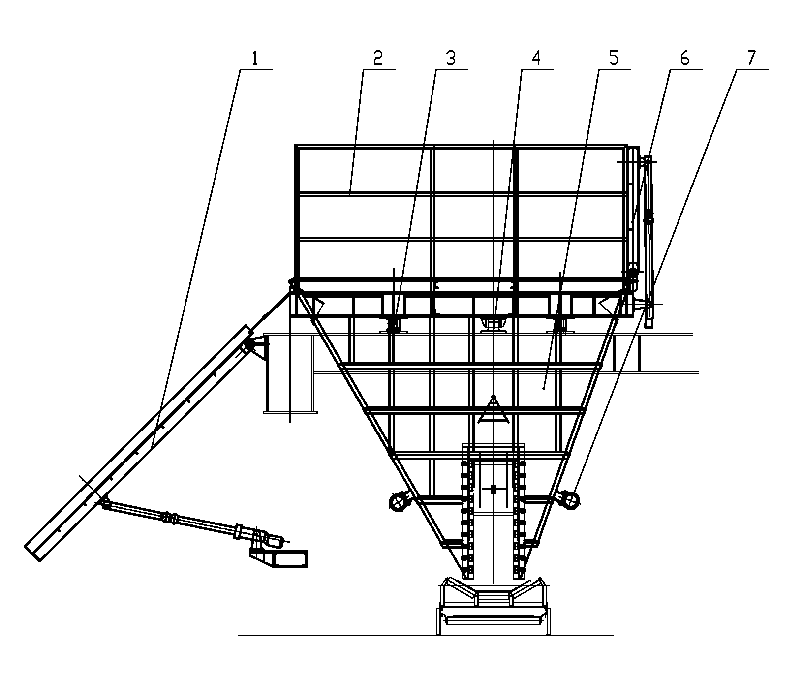
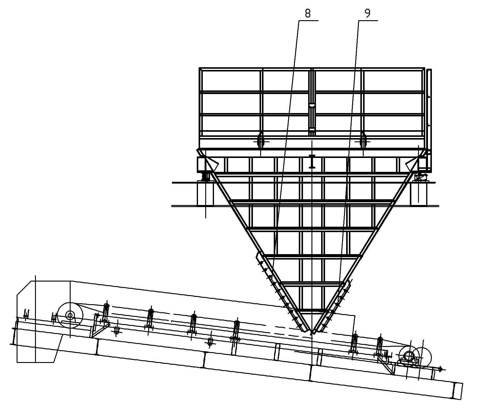
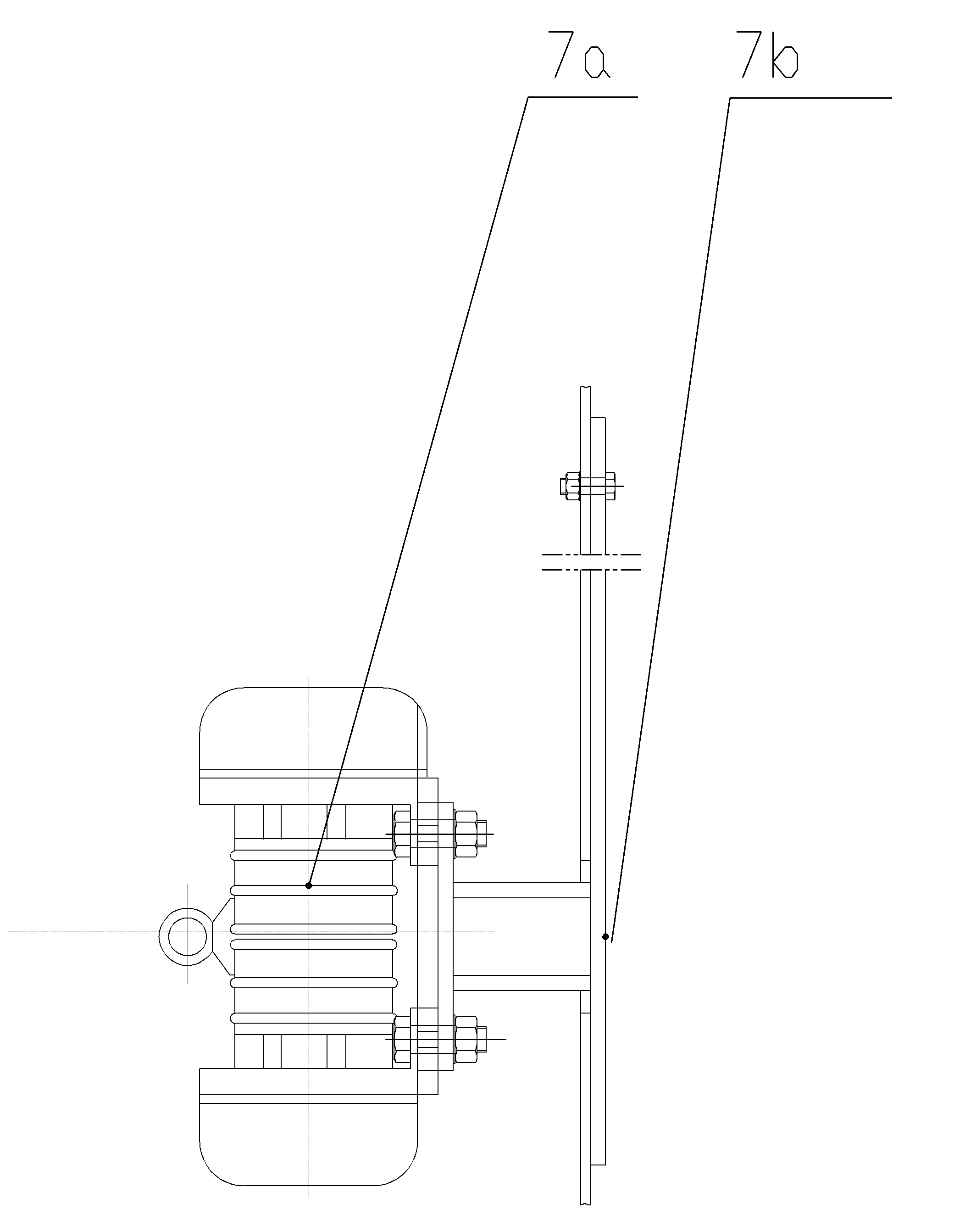
[0018] Figure 1 to Figure 6 As shown, it includes material receiving plate 1, side windshield 2, weighing load unit 3, anti-deflection device 4, hopper body 5, rear windshield 6, bin wall vibrator 7, main bucket door 8, auxiliary bucket door 9 .

[0019] like figure 1 As shown, the material receiving plate 1 is arranged at the upper mouth of the hopper body 5; the side windshields 2 are respectively fixed on both sides of the edge perpendicular to the shoreline at the upper mouth of the hopper body 5; the weighing load unit 3 and the anti-deflection device 4 are all arranged under the support beam of the hopper body 5; the rear windshield 6 is arranged on the upper opening of the hopper body 5; And auxiliary bucket door 9 are respectively arranged on both sides of the hopper discharge opening.

[0020] Wherein said weighing load unit 3 is...


PUM


Abstract

The invention relates to a self-weighing hopper of a loading and unloading device. The self-weight hopper is mainly characterized in that a material collecting plate is arranged at an upper hole of a hopper body of the hopper, side windshield plates are respectively fixed on both sides of an edge of the upper hole of the hopper body of the hopper, and the edge is perpendicular to a shoreline; a weighing load unit and an anti-deflexion device are both arranged under a supporting beam of the hopper body of the hopper; a rear windshield plate is arranged at the upper hole of the hopper body of the hopper; bin-wall vibrators are respectively arranged on both sides of a hopper wall without a hopper door at the middle lower part of the hopper body; a main hopper door and a secondary hopper door are respectively arranged on both sides of a discharging hole of the hopper; a vibrating motor of each bin-wall vibrator is connected with a built-in vibration plate by a motor installing bracket, the built-in vibration plate is fixed on the inner side of the hopper wall of the hopper by bolts, and a safe lifting lug and a safe chain are hung on the vibrating motor. In the invention, the weighing load unit has high precision; the structure modes of the main hopper door and the secondary hopper door avoid the phenomena of material blockage, and the like due to poor fluidity of materials; and compared with the traditional vibrating motor, the built-in vibration plate is directly arranged on the hopper wall in order to more effectively vibrate and disperse blocked materials.

Description

technical field [0001] The invention belongs to the technical field of construction machinery, and relates to an improved technology for loading and unloading equipment with a load-bearing hopper, which is mainly aimed at the load-bearing hopper equipment for unloading materials with poor fluidity. Background technique [0002] With the economic development, the port construction is advancing by leaps and bounds. The demand for loading and unloading equipment such as ship unloaders and container quay cranes is increasing. Generally, bulk materials are measured by the belt scale on the belt conveyor in the port corridor. However, since the belt scale weighs fluid materials, the accuracy is low. When it is used alone, disputes between buyers and sellers often arise on the measurement results. In this regard, the weighing hopper is generally used to weigh the material to check the accuracy of the belt scale. And because there are many kinds of materials, especially those con...

Claims


Application Information

Patent Timeline
Patent Type & Authority Applications(China)
IPC IPC(8): B65D88/66B65G65/00
Inventor 李钟王兵龚伟沈琦
Owner 无锡工力工程机械厂
Why Eureka
Eureka Blog
Learn More