Thermal control method and system based on capillary slot group and thermal power combination

A technology of micro-groove group and thermal control, applied in the direction of circuits, electrical components, indirect heat exchangers, etc., can solve the problems of low efficiency, insufficient heat dissipation, large lasers, etc.

Inactive Publication Date: 2008-08-13
INST OF ENGINEERING THERMOPHYSICS - CHINESE ACAD OF SCI
View PDF0 Cites 29 Cited by
  • Summary
  • Abstract
  • Description
  • Claims
  • Application Information

AI Technical Summary

Problems solved by technology

[0013] The purpose of the present invention is to: solve the technical defects of low efficiency existing in the existing heat dissipation technology, need to occupy relatively large lasers, limited functional space of electronic and electrical and other optoelectronic systems, insufficient heat dissipation capacity, and poor thermal control performance; thereby providing a No power consumption, small area, high heat flux density heat extraction mode, at the same time, meet the operating temperature requirements of heating components lower than ambient temperature, can perform high-precision temperature control on heating components and have strong heat dissipation capacity Micro slot group and thermoelectric cooler (TEC) combined heat dissipation and thermal control system

Method used


Image

  • Thermal control method and system based on capillary slot group and thermal power combination
  • Thermal control method and system based on capillary slot group and thermal power combination
  • Thermal control method and system based on capillary slot group and thermal power combination

Examples


Embodiment 1

[0072] Below in conjunction with accompanying drawing and embodiment the present invention is described in detail:

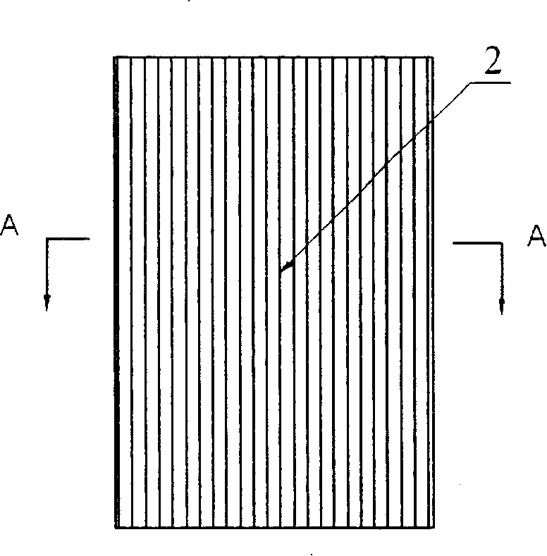
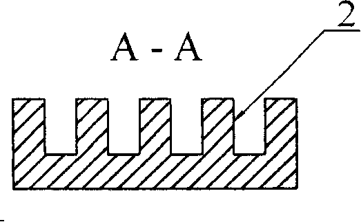
[0073] see Figure 5 , to make a water-cooled heat dissipation capillary microgroove group and thermoelectric cooler (TEC) combined heat dissipation and thermal control system. It includes a micro-groove group evaporator 3 with a rectangular sealed cavity made of metal copper with good thermal conductivity, which can also be called a heat-taking element. The inner wall of the micro-groove group evaporator 3 cavity has a rectangular micro-groove 2 to form a micro-groove group. The spacing of the micro-groove 2 is 0.4mm, the width of the micro-groove 2 is 0.3mm and the groove The depth is 0.8mm. The size of described rectangular micro-channel 2 is suitable for forming stronger capillary force, so that dehydrated alcohol or distilled water etc. in the micro-groove group evaporator 3 have higher vaporization latent heat liquid working medium through micro-channel ...

Embodiment 2

[0078] see Figure 6, to make a combined heat dissipation and thermal control system of air-cooled heat dissipation capillary microgroove group and thermoelectric cooler (TEC). The water-cooled radiator in Embodiment 1 is replaced by a radiator plate 8 with fin groups. The hot surface of the thermoelectric cooler is in close contact with the bottom surface of the heat sink plate 8 with fins through the heat conducting silicone grease, and a fan 9 is installed on the top of the heat sink plate 8. The height of the rectangular fins is 20 mm, and the thickness of the fins is 1 mm. , the fin spacing is 1.5mm, the power of the fan 9 is 30W, the heat released by the condensation of the steam is conducted from the inner wall of the condenser 6 to the outer surface of the condenser 6, and is absorbed by the cold surface of the thermoelectric cooler. While performing temperature control, the heat and the heat generated by the thermoelectric cooler itself are conducted from the hot sur...

Embodiment 3

[0079] Embodiment 3: In this embodiment, a capillary wick is installed in the liquid return hose 10 along the direction of the tube axis to increase the capillary force for the condensate to quickly flow back to the evaporator. The capillary core is a 2-layer 250-mesh stainless steel wire mesh core. Other parts of this embodiment are the same as Embodiment 1.


PUM


Abstract

The invention is a capillary microgrooves and thermoelectric combined heat control method and system, relates to a heat dissipation and heat controlling method and device used in laser, electronic and electric apparatus. Liquid are heated for evaporation and boiling in capillary microgroove evaporator by heat member, steam flows into condensator through heat preservation flexible pipe, coagulates and heat releases in coagulating microgrooves in condensator under function of thermoelectric cooler on exine of condensator, and meanwhile thermoelectric cooler transmit heat from heat surface to heat dissipation elements (heat dissipation board or water-cooling heat radiator), and finally dissipate heat by air-cooling or water-cooling; coagulated liquid flows back to capillary microgroove evaporator through liquid return flexible pipe and connector to drain microgrooves, so that a circulation of heat extracting and releasing is completed, and components are cooled and heat controlled. Device adopting the inventive method includes a vacuum capillary microgroove evaporator, heat preservation flexible pipe, condensator, thermoelectric cooler, heat dissipation element, liquid return flexible pipe, connector to drain microgrooves.

Description

technical field [0001] The invention relates to a heat dissipation and thermal control system for laser devices, electronic and electrical components and other optoelectronic devices, in particular to capillary micro- Combined heat dissipation and thermal control system of tank group and thermoelectric cooler (TEC). Background technique [0002] High-power lasers are essential equipment for high-precision machining and important weapons and equipment. They have extensive and significant application values ​​in laser processing, information and military fields. However, the improvement of the laser output power of the laser is severely restricted by the heat dissipation performance and thermal control performance of the laser. Generally, only 5% of the input energy of a general flash pump source laser can be converted into laser output, and the rest must be converted into heat energy and other forms of energy. For example, if 1kw of electric energy is input, only 50w of lase...

Claims


Application Information

Patent Timeline
Patent Type & Authority Applications(China)
IPC IPC(8): H05K7/20H01S3/04H01S5/024
CPCF28D15/0266F28D15/046
Inventor 胡学功唐大伟肖送连王涛
Owner INST OF ENGINEERING THERMOPHYSICS - CHINESE ACAD OF SCI
Why Eureka
Try Eureka