Spherical door and bidirectional synchronous opening and closing driving device for same

A spherical door and spherical technology, applied to the suspension device of the wing leaf, the arrangement of the wing leaf, door/window accessories, etc., can solve the problems of unusable and other problems, and achieve the effect of fast opening and closing, beautiful appearance and high efficiency

Inactive Publication Date: 2011-01-05
NINGBO UNIV
View PDF5 Cites 6 Cited by
  • Summary
  • Abstract
  • Description
  • Claims
  • Application Information

AI Technical Summary

Problems solved by technology

At present, the structural form of the door is usually flat, and the movement form of the flat door is usually plane movement or rotation, so as to realize the opening and closing of the flat door. In addition, the gates of buildings such as hotels and office buildings are often Revolving doors are used to facilitate people's entry and exit, but in some special applications, such as spherical piles, spherical landscape buildings, etc., the above-mentioned flat doors and revolving doors cannot be used

Method used


Image

  • Spherical door and bidirectional synchronous opening and closing driving device for same
  • Spherical door and bidirectional synchronous opening and closing driving device for same
  • Spherical door and bidirectional synchronous opening and closing driving device for same

Examples


Embodiment 1

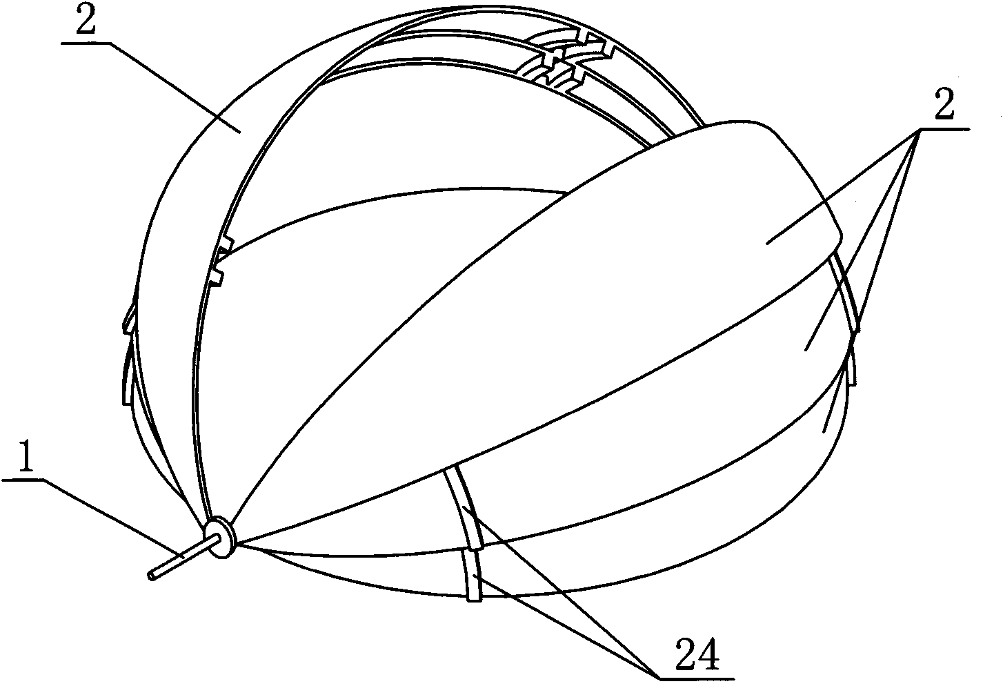
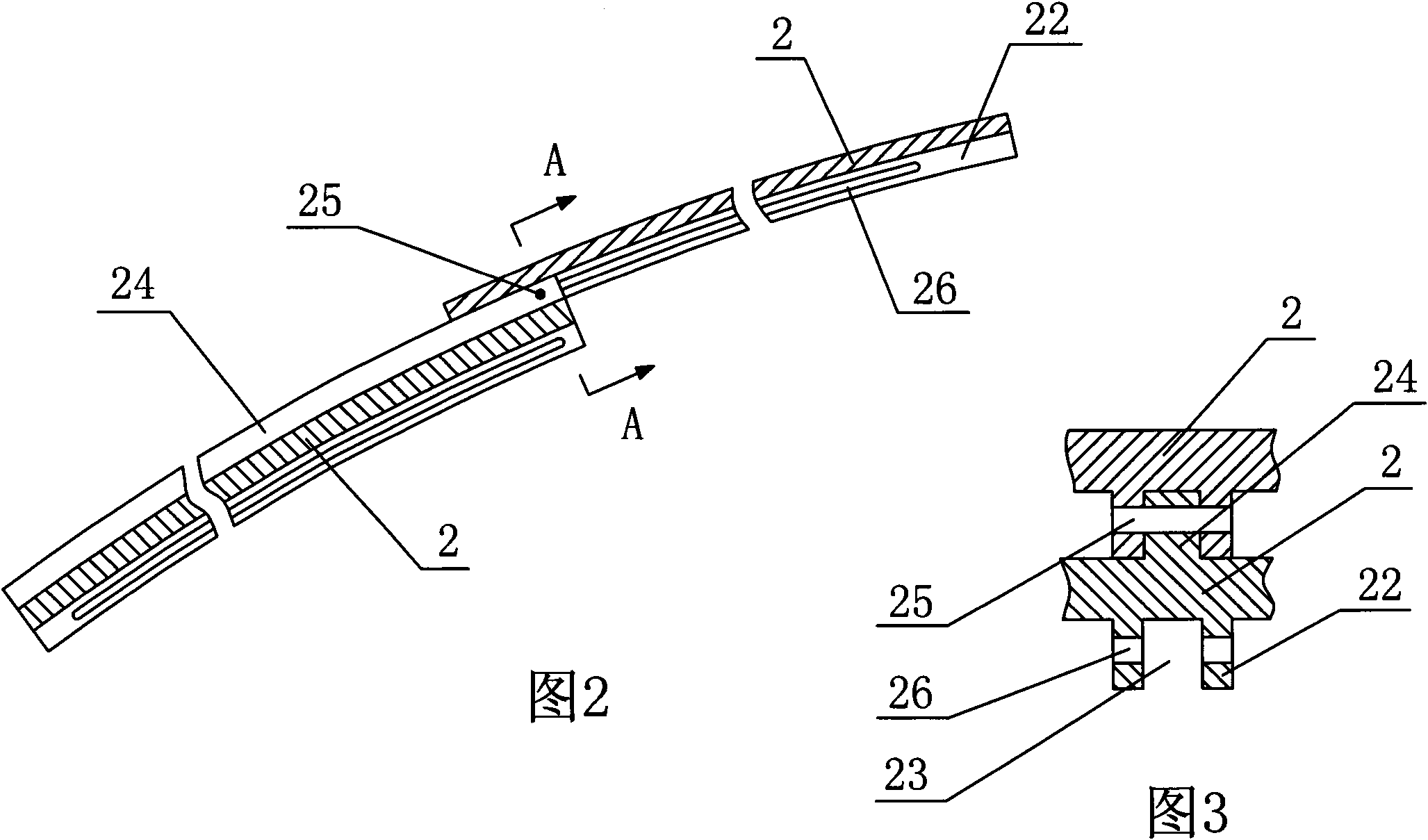
[0019] Embodiment 1: As shown in the figure, a spherical door includes two sets of symmetrically arranged spherical blade groups. Spherical blades 2, a sliding mechanism arranged along the opening and closing track of the spherical door is arranged between two adjacent spherical blades 2, the sliding mechanism includes an arc-shaped slider 24 arranged on the outer surface of the inner spherical blade 2, and the outer spherical blade Two parallel arc-shaped ribs 22 are arranged on the inner surface of 2, and an arc-shaped chute 23 is formed between the two arc-shaped ribs 22. The arc-shaped slider 24 matches the arc-shaped chute 23, and the arc-shaped The upper end of the slider 24 is fixedly provided with a connecting pin 25 placed horizontally, and the arc-shaped rib 22 is provided with an arc-shaped connecting hole 26 closed at both ends, and the connecting pin 25 and the arc-shaped connecting hole 26 are slidably fitted.

Embodiment 2

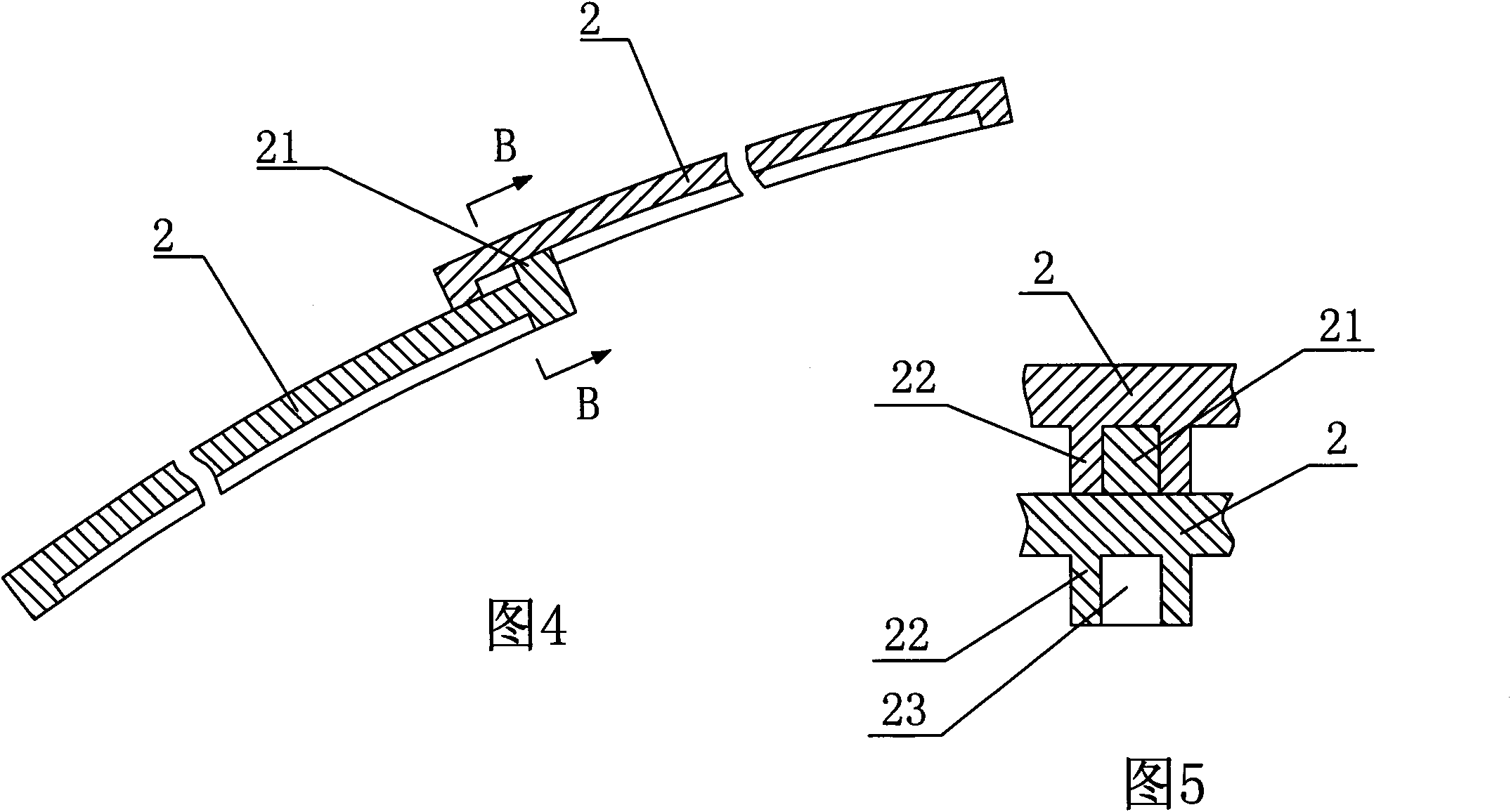
[0020] Embodiment two: as shown in the figure, other structures are the same as embodiment one, and the difference is that the sliding mechanism includes a slider 21 arranged on the upper end of the outer surface of the inner spherical blade 2, and the inner surface of the outer spherical blade 2 is provided with two Parallel arc-shaped ribs 22, an arc-shaped chute 23 is formed between the two arc-shaped ribs 22, the two ends of the arc-shaped chute 23 are closed, and the slide block 21 matches the arc-shaped chute 23.

[0021] As shown in the figure, the two-way synchronous opening and closing drive device of the above-mentioned spherical door includes a motor 3, a screw rod 4, a support plate 6 and two rotating rods 5, the motor 3 is connected with the screw rod 4 through a reducer, and the screw rod 4 is set There are left-handed threads and right-handed threads, the screw mandrel 4 is screwed with a left drive nut 41 through a left-handed thread, and a right drive nut 42 is...


PUM


Abstract

The invention discloses a spherical door. The spherical door comprises two symmetrically-arranged spherical blade groups, wherein the two end parts of the two symmetrically-arranged spherical blade groups are connected with a spindle respectively; each spherical blade group comprises at least two spherical blades; and a sliding mechanism which is arranged along an opening and closing track of the spherical door is arranged between two adjacent spherical blades. The spherical door has the advantages that: the spherical door consists of the two symmetrically-arranged spherical blade groups, is semispherical after being closed and suitable for certain special application occasions such as spherical piles, spherical landscape buildings and the like, can also be taken as a spherical cap on a roof ceiling and has attractive appearance; and the sliding mechanism which is arranged along the opening and closing track of the spherical door is arranged between the two adjacent spherical blades and lower spherical blades can be driven to move by driving uppermost spherical blades to move, so that the spherical door can be opened and closed freely.

Description

technical field [0001] The invention relates to a door and its driving device, in particular to a spherical door and a bidirectional synchronous opening and closing driving device of the spherical door. Background technique [0002] Doors are an integral part of all kinds of architecture. At present, the structural form of the door is usually flat, and the movement form of the flat door is usually plane movement or rotation, so as to realize the opening and closing of the flat door. In addition, the gates of buildings such as hotels and office buildings are often Revolving doors are used to facilitate people's entry and exit, but in some special applications, such as spherical piles, spherical landscape buildings and other places, the above-mentioned flat doors and revolving doors cannot be used. Contents of the invention [0003] The technical problem to be solved by the present invention is to provide a spherical door suitable for use in some special applications and a ...

Claims


Application Information

Patent Timeline
Patent Type & Authority Applications(China)
IPC IPC(8): E06B3/42E05F15/10E05D13/00E05F15/603
Inventor 孙宝寿束学道陈哲吴真繁
Owner NINGBO UNIV
Why Eureka
Try Eureka