Upper buckle positioning device

A technology of positioning device and buckle groove, which is applied in the direction of tools for sewing clothes, etc., can solve the problems of positioning device damage, increased workload, and high cost of use, and achieve the effects of reducing cost of use, prolonging service life, and simple structure

Inactive Publication Date: 2011-01-12
ZHENGZHOU UNIV
View PDF4 Cites 0 Cited by
  • Summary
  • Abstract
  • Description
  • Claims
  • Application Information

AI Technical Summary

Problems solved by technology

This type of buckle support and positioning device has the following disadvantages: 1. When punching, relying on the impact force of the punch to force the buckle support and positioning device to release the buckle, the buckle support a

Method used


Image

  • Upper buckle positioning device
  • Upper buckle positioning device
  • Upper buckle positioning device

Examples


Embodiment Construction

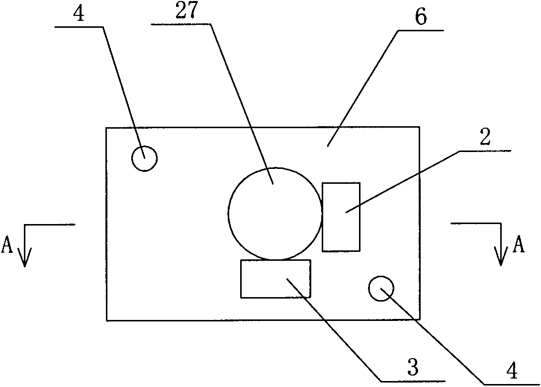
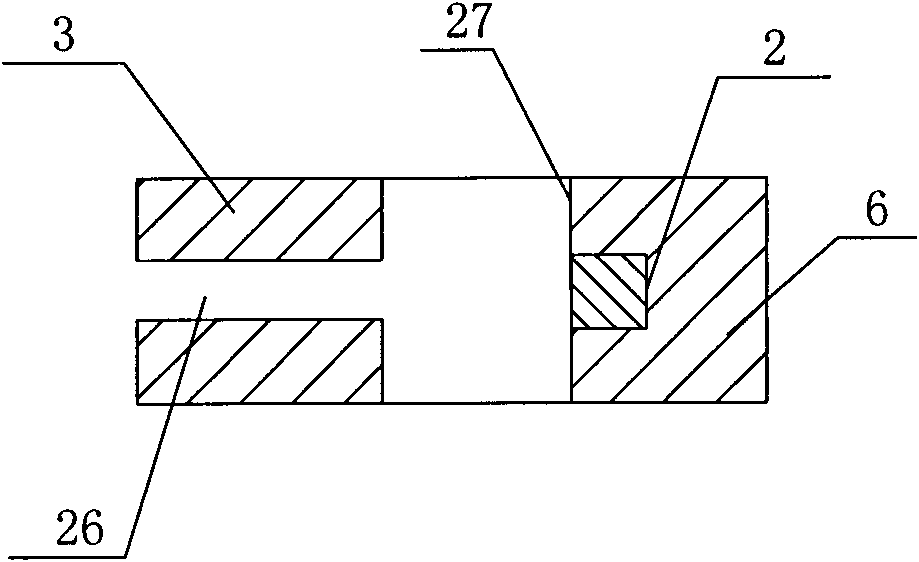
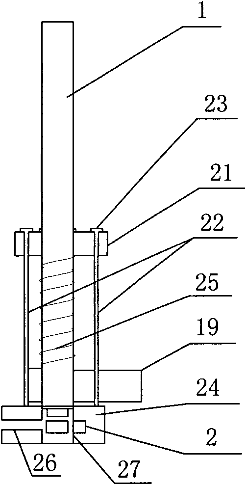
[0017] Such as figure 1 with figure 2 As shown, the buckle positioning device of the present invention includes a plate body 6. The plate body 6 is provided with punched through holes 27 up and down. The middle of the punched through holes 27 is connected with a horizontally arranged upper buckle groove 26. The upper buckle groove 26 opens in One side of the plate body 6; in the plate body 6 adjacent to the punched through hole 27, a first permanent magnet 2 and a second permanent magnet 3 are embedded, and the first permanent magnet 2 is located at the punched through hole 27 on the opposite side of the upper buckle groove 26 Where, the second permanent magnet 3 and the first permanent magnet 2 are distributed at right angles along the circumferential direction of the punched through hole 27. Wherein, the first permanent magnet 2 and the second permanent magnet 3 are both tangent to the punched through hole 27; the plate body 6 is a rectangular plate body, and guide rods are r...


PUM


Abstract

The invention discloses an upper buckle positioning device, comprising a plate body. The inner of the plate body is provided with a through stamping hole from the top to the bottom, the middle part of the stamping hole is horizontally provided with an upper buckle groove in communication, the upper buckle groove is opened on one side of the plate body, and a permanent magnet is embedded adjacent to the stamping hole in the plate body. The device of the invention has simple structure and convenient use. Due to that the upper buckle is supported and positioned by the magnetic force without the direct using of solid support component, a stamping vertical bar can press the upper buckle down without the direct stamping on the upper buckle positioning device when stamping, thereby avoiding the mechanical shock when stamping the upper buckle positioning device and achieving more stable operation of the dotter. Meanwhile, the upper buckle positioning device can not be damaged due to the bearing of the impacting force, thereby prolonging the service life of the device greatly, saving the work load for changing the upper buckle positioning device as well as reducing the use cost.

Description

Technical field [0001] The invention relates to a buckle positioning device of a buckle machine. Background technique [0002] The buckle support and positioning devices of the existing buckle machine use movable parts to support the buckle, and the movable part moves and releases the buckle when buckling. For example, the Chinese patent application with the application number 200710066820.0 discloses a "punch of an automatic buckle machine and an automatic buckle method". The technical solution disclosed in the patent application adopts a buckle support opening composed of two punch chucks to support , Positioning the upper buckle, when the punch is punched downwards, the punch at the lower end of the punch directly impacts the upper buckle and the punching buckle opening. Under the impact force, the punching buckle opening is forced to open, thereby releasing the upper buckle. Allow the top button to fall. This type of upper buckle support and positioning device has the follo...

Claims


Application Information

Patent Timeline
IPC IPC(8): A41H37/00
Inventor 刘占卫田金毓鲁大勇吕芳李金固
Owner ZHENGZHOU UNIV
Why Eureka
Try Eureka