Check patentability & draft patents in minutes with Patsnap Eureka AI!

Passengers conveying apparatus

A technology of passenger conveying equipment and guide rails, which is used in transportation and packaging, escalators, etc., can solve the problems of falling off of fixed parts, insufficient fixing force, contact of connecting members, etc., and achieve the effect of ensuring safety.

Inactive Publication Date: 2011-01-12
HITACHI LTD
View PDF8 Cites 11 Cited by
  • Summary
  • Abstract
  • Description
  • Claims
  • Application Information

AI Technical Summary

Problems solved by technology

However, in the passenger conveying equipment disclosed in Patent Document 2, due to vibration and impact forces during transportation and operation, etc., the fixing force between the left and right guide rail support members and the connecting members may be insufficient, and the fixing parts may fall off. As a result, the connecting member falls and comes into contact with members such as steps

Method used


Image

  • Passengers conveying apparatus
  • Passengers conveying apparatus
  • Passengers conveying apparatus

Examples


no. 1 approach

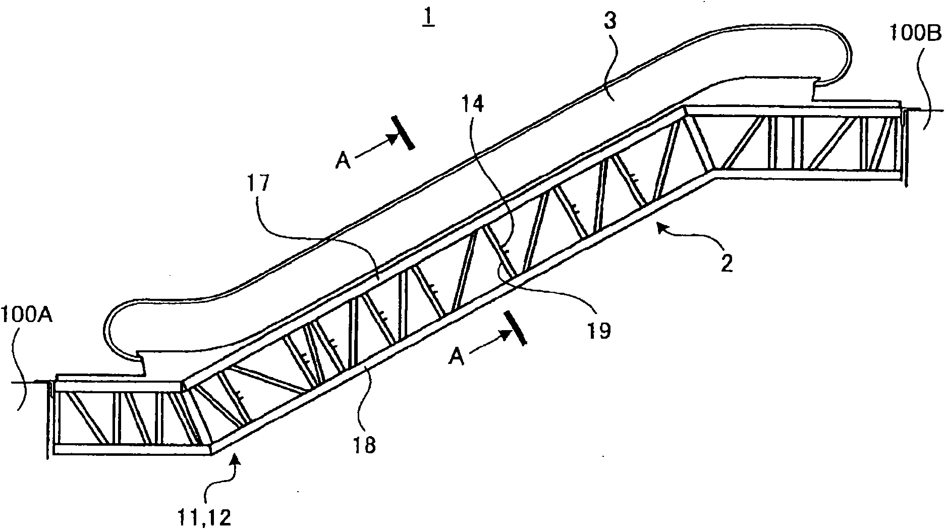
[0050] First refer to figure 1 with figure 2 A first embodiment of the passenger conveying facility of the present invention will be described.

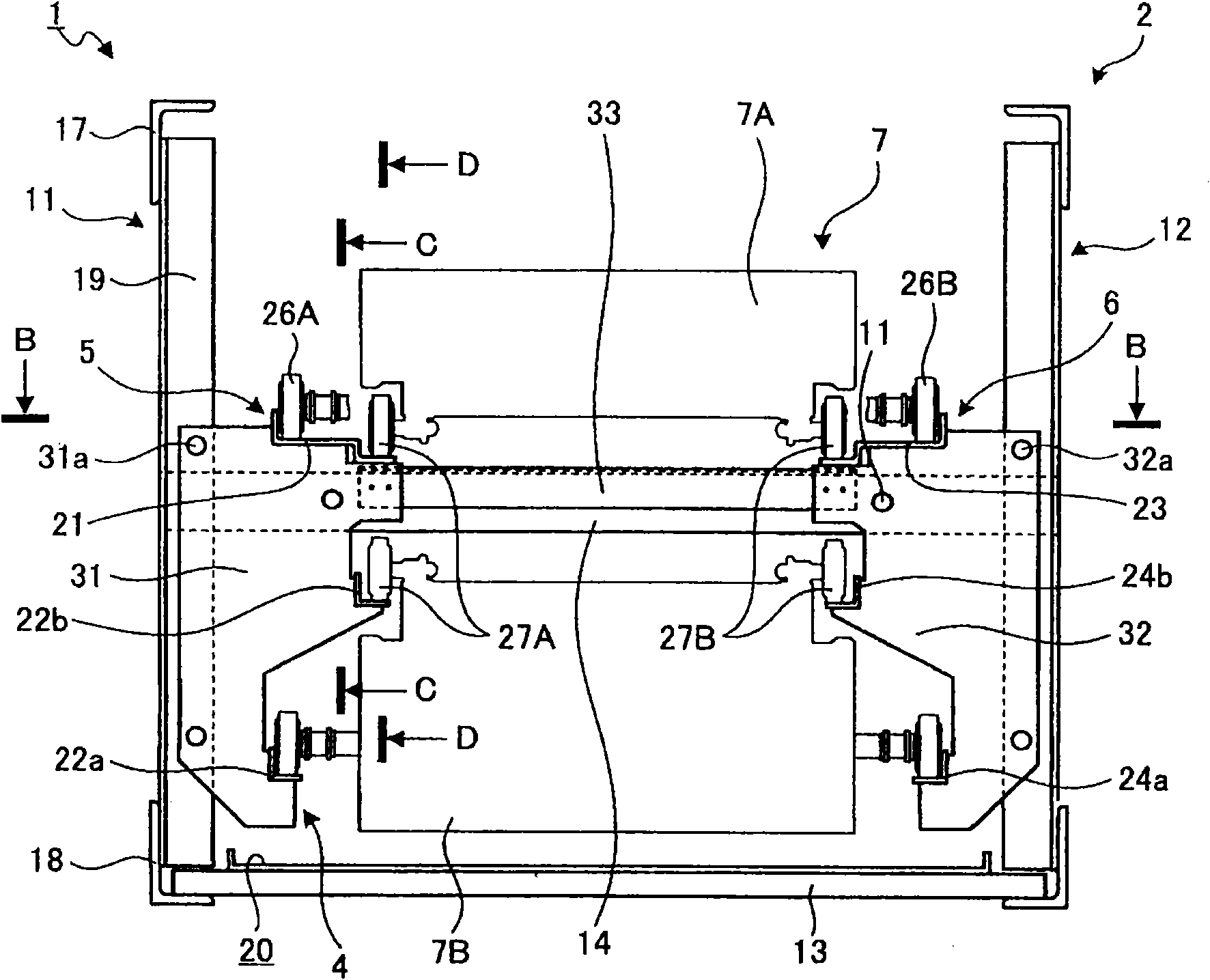
[0051] figure 1 It is a schematic configuration diagram showing the first embodiment of the passenger conveying facility of the present invention. figure 2 is along figure 1 Sectional view of line A-A.

[0052] The passenger conveying facility 1 is a so-called escalator which is an inclined passenger conveying facility installed between a lower floor 100A and an upper floor 100B of a building. This passenger conveying apparatus 1 has a truss 2 , a railing portion 3 , a rail support unit 4 , a first rail 5 and a second rail 6 , and a plurality of steps 7 .

[0053] The trusses 2 are installed across the lower floor 100A and the upper floor 100B. Hereinafter, the width direction of the truss 2 when viewing the truss 2 from 100 A of lower floor floors is made into the left-right direction. The truss 2 is used to support the rai...

no. 2 approach

[0089] Next, refer to Figure 9 with Figure 10 A second embodiment of the passenger conveyor facility according to the present invention will be described.

[0090] Figure 9 It is a cross-sectional view showing the second embodiment of the passenger conveying facility of the present invention. Figure 10 is along Figure 9 Sectional view of E-E line.

[0091] The passenger conveying facility 51 of the second embodiment has the same structure as the passenger conveying facility 1 of the first embodiment described above. This passenger conveyor 51 differs from the passenger conveyor 1 only in the rail support unit 54 . The guide rail support unit 54 will be described below, and the same parts as those of the passenger conveyor 1 will be denoted by the same symbols, and repeated description will be omitted.

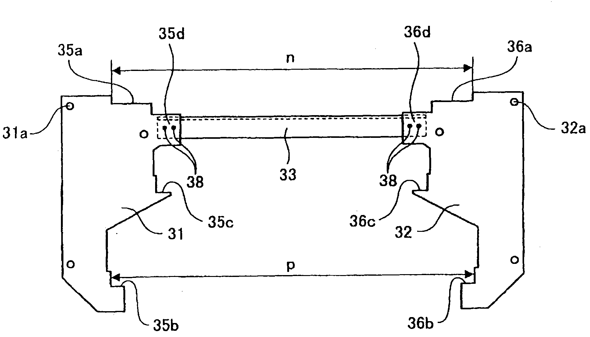
[0092] The rail supporting unit 54 is composed of a first rail supporting member 31 supporting the first rail 5, a second rail supporting member 32 supporting the se...


PUM


Abstract

The invention provides a passengers conveying apparatus which is capable of preventing a connecting component from falling off, and the connecting component is not contacted with a stair component even under the condition that a fixing part between a rail support component and the connecting component is fallen off, thereby ensuring the safety of the passengers. The passengers conveying apparatus (1) is provided with a girder (2), a rail support unit (4), a first rail (5), a second rail (6), and a plurality of stairs (7). The girder (2) is arranged in the building; the girder (2) is provided with the rail support unit (4). The rail support unit (4) is provided with a first rail support component (31) for supporting the first rail (5), a second rail support component (32) for supporting the second rail (6) and the connecting component (33) for connecting both of the first rail support component (31) and the second rail support component (32). The connecting component (33) of the rail support unit (4) prevents the movement caused by gravity through blocking with the girder (2). The plurality of stairs (7) are in annular connection and circularly move between a going side and a returning side under the lead of the first rail (5) and the second rail (6).

Description

technical field [0001] The present invention relates to passenger conveying equipment such as an escalator with a level difference between the steps and a moving walkway with no level difference between the steps. Background technique [0002] In general, a passenger conveyor has a truss provided across an upper floor and a lower floor, a plurality of guide rails mounted on the truss, and a plurality of steps that circulate and move under the guidance of the plurality of guide rails. In the above-mentioned passenger conveying equipment, in order to prevent the steps from vibrating, it is necessary to mount a plurality of guide rails on the truss with high precision. [0003] As a conventional passenger conveyor, for example, there is known a scheme disclosed in Patent Document 1, which makes two truss members each having a rail support portion face each other in a direction perpendicular to the moving direction of the steps, and in this In this state, the two truss members ...

Claims


Application Information

Patent Timeline
IPC IPC(8): B66B23/00
Inventor 堀江宣孝中山泰幸薄井崇广
Owner HITACHI LTD
Features
  • R&D
  • Intellectual Property
  • Life Sciences
  • Materials
  • Tech Scout
  • Unparalleled Data Quality
  • Higher Quality Content
  • 60% Fewer Hallucinations
Learn More