Antenna mounting frame

A technology for mounting brackets and antennas, which is applied in the direction of antennas, antenna supports/mounting devices, electrical components, etc., and can solve problems such as easy deviation from required angles, decreased positioning accuracy, and angle offsets, so as to save labor and improve accuracy Controlled, easy-to-control effects

Inactive Publication Date: 2011-01-12
深圳市前海滕翔科技信息有限公司
View PDF3 Cites 25 Cited by
  • Summary
  • Abstract
  • Description
  • Claims
  • Application Information

AI Technical Summary

Problems solved by technology

[0005] During the research process of the present invention, the inventor found that the structure of the above-mentioned antenna mounting frame has the following defects: when the operator adjusts the downtilt angle of the antenna, it is difficult to accurately control the adjustment angle, which leads to the repeated execution of the adjustment operation and is time-consuming, and cannot Guaranteed precise positioning of the downtilt
The reason why it is difficult to accurately control the adjustment angle is that when the operator applies force to the adjustment component to adjust the angle, he also needs to support the gravity of the antenna. The gravity of the anten

Method used


Image

  • Antenna mounting frame
  • Antenna mounting frame
  • Antenna mounting frame

Examples


no. 1 example

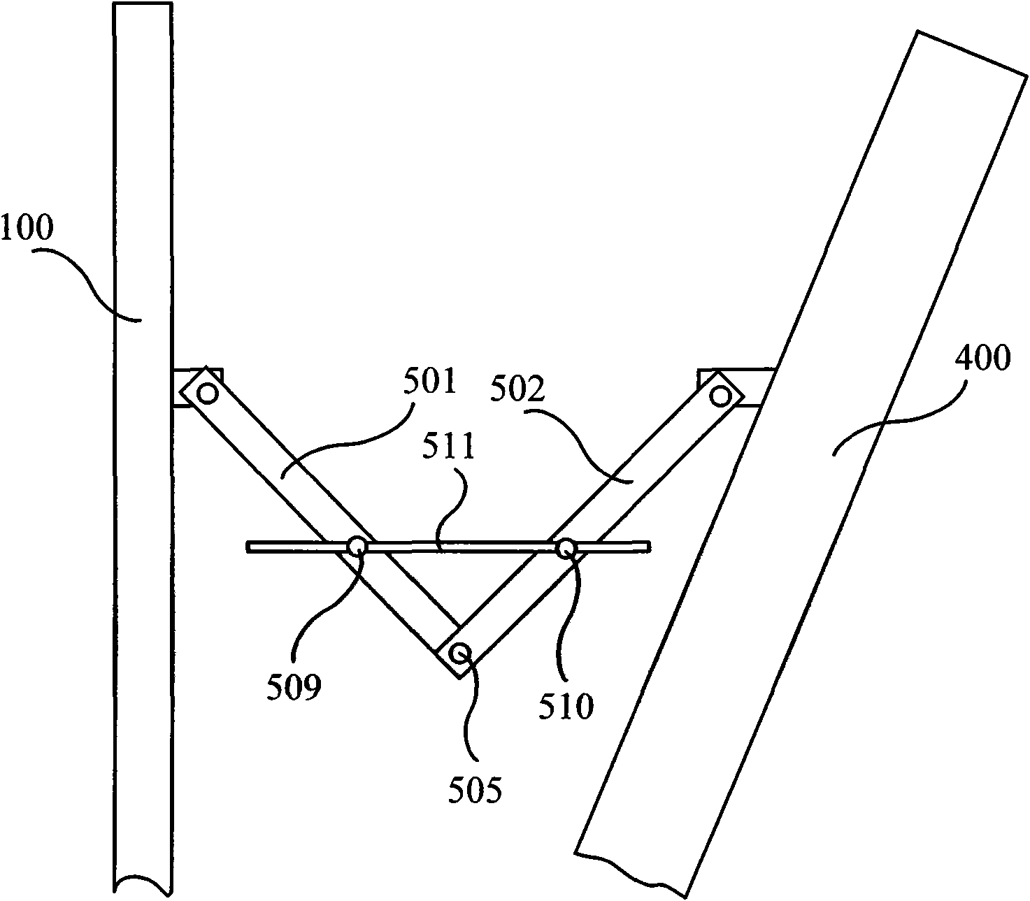
[0047] figure 2 It is a schematic structural diagram of the adjustment assembly in the antenna mounting frame provided by the first embodiment of the present invention. The antenna installation frame of this embodiment includes an adjustment assembly connected between the antenna 400 and the support body 100 , and the adjustment assembly includes: an adjustment arm and an adjustment screw 511 . In this embodiment, the number of adjusting arms is two, that is, the first adjusting arm 501 and the second adjusting arm 502, and the first adjusting arm 501 and the second adjusting arm 502 are connected to each other with the first pivot shaft 505 as the connecting shaft, And can be relatively rotated in an adjustment plane, the antenna 400 and the support body 100 can be respectively connected with the first adjustment arm 501 and the second adjustment arm 502 . The adjustment plane is the plane where the plane hinge structure formed by the first adjustment arm 501 and the second...

no. 2 example

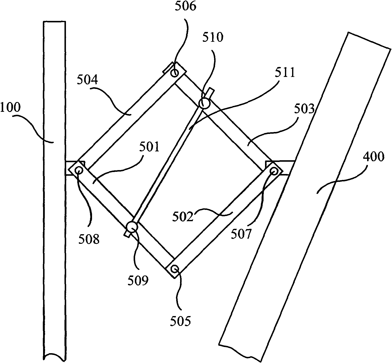
[0051] image 3 It is a schematic structural diagram of the adjustment assembly in the antenna mounting bracket provided by the second embodiment of the present invention. The antenna installation frame of this embodiment includes an adjustment assembly connected between the antenna 400 and the support body 100 , and the adjustment assembly includes: an adjustment arm and an adjustment screw 511 . The number of adjusting arms is four, that is, the first adjusting arm 501, the second adjusting arm 502, the third adjusting arm 503 and the fourth adjusting arm 504, and the four adjusting arms are connected to each other by two pairs of four pivot shafts respectively. like image 3 As shown, the first adjusting arm 501 and the second adjusting arm 502 are rotatably connected through the first pivot shaft 505, the second adjusting arm 502 and the third adjusting arm 503 are rotatably connected through the third pivot shaft 507, and the third adjusting arm 503 The fourth adjusting...

no. 3 example

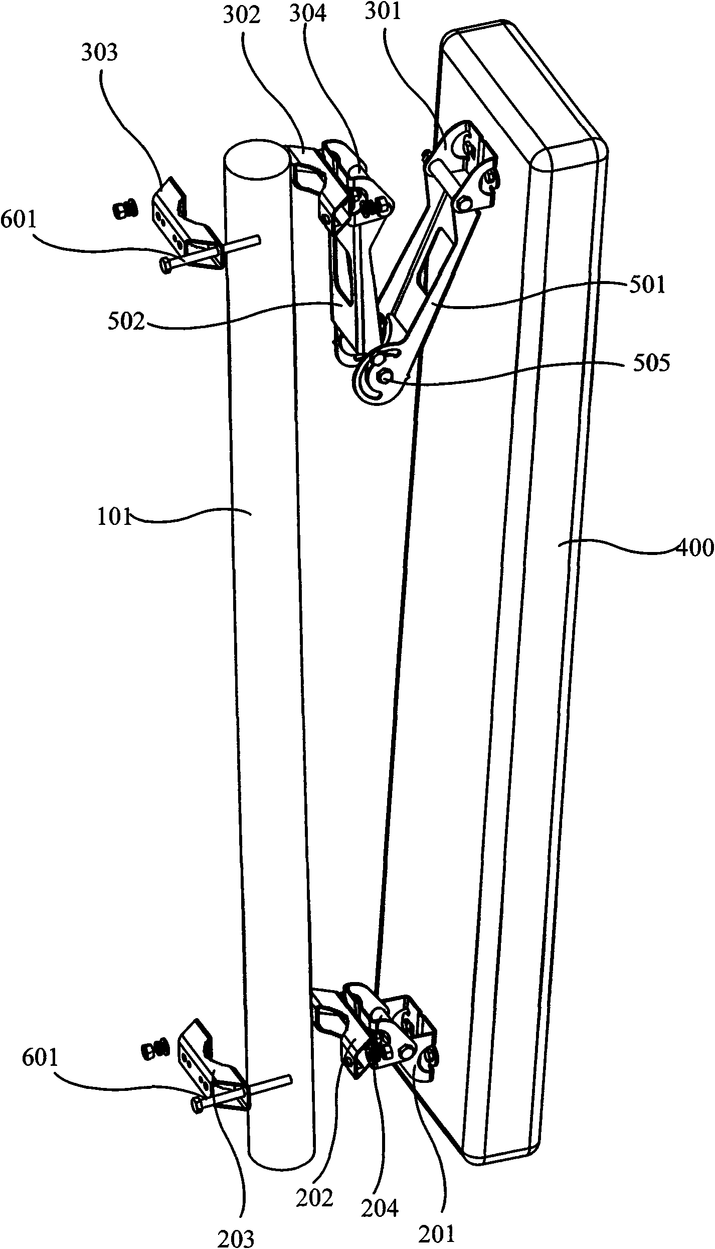
[0059] Figure 4It is a schematic structural diagram of the antenna mounting frame provided by the third embodiment of the present invention, and specifically shows a disassembled structure in a ready-to-assemble state. The antenna mounting frame includes an adjustment assembly, and the adjustment assembly can use the technical solution provided by the above-mentioned first or second embodiment. In this embodiment, the structure of the adjustment assembly of the four adjustment arms provided by the second embodiment is used as an example for illustration. . The adjustment assembly is connected between the antenna 400 and the support body 100 through the upper assembly, and a lower assembly is also connected between the antenna 400 and the support body 100 .

[0060] Specifically, the lower assembly includes a first lower mounting part 205 , a second lower mounting part 206 and a third rotating shaft 207 . The first lower mounting part 205 is used to be fixedly connected to t...


PUM


Abstract

The invention provides an antenna mounting frame, comprising an adjustment assembly connected between an antenna and a support. The adjustment assembly is a plane hinge structure formed by at least three shaft levers connected with each other by using articulation shafts as connection shafts and the plane hinge structure has a degree of freedom, wherein one shaft lever is an adjustment screw and the other shaft levers are adjustment arms; at least two articulation shafts connected with the adjustment screw are a first rotation shaft and a second rotation shaft, respectively; the adjustment screw is in threaded screw connection with one of the first and the second rotation shafts, and in threaded screw connection or fixed connection in the direction of the adjustment screw with the other. The invention adopts the rotation action of the threaded screw to change the relative positions of the adjustment arms, and can improve the adjustment precision through decreasing the acting force, adjusting continuously and having self-locking function.

Description

technical field [0001] Embodiments of the present invention relate to antenna installation technologies, and in particular to an antenna installation frame. Background technique [0002] Antennas usually need to be fixed on a support to receive signals. In order to obtain a good reception effect, many antennas are fixed on high places outdoors, such as iron towers, roof towers, etc., and the installation angle of the antenna needs to be adjusted according to the requirements of the received signal. Therefore, the existing antenna mounting frame is generally Both have adjustment components capable of adjusting the angle. [0003] figure 1 It is a schematic structural diagram of an antenna mounting frame in the prior art, and shows a state to be assembled. like figure 1 As shown, the installation frame includes a lower assembly, an upper assembly and an adjustment assembly, which are used to install the antenna 400 on the steel pole 101 . Wherein, the lower assembly inclu...

Claims


Application Information

Patent Timeline
IPC IPC(8): H01Q1/12H01Q3/02H01Q3/06
Inventor 张铁胜王显军黄茂胜陈海平王彬
Owner 深圳市前海滕翔科技信息有限公司
Why Eureka
Try Eureka