Loudspeaker

A loudspeaker and casing technology, which is applied in the field of small or micro loudspeakers, can solve the problems of hearing loss, high requirements of designers, and reduce the power of bone conduction loudspeakers, so as to reduce the impact and protect hearing

Inactive Publication Date: 2011-01-12
陈奚平
View PDF1 Cites 14 Cited by
  • Summary
  • Abstract
  • Description
  • Claims
  • Application Information

AI Technical Summary

Problems solved by technology

Although this invention can protect the user's hearing, and also reduces the power of the bone conduction speaker, so that it can be directly connected with various portable devices, but the timbre is not perfect due to the characteristics of the bone conduction speaker , especially in the low and high frequency bands
Moreover, since the mechanical inertia of the vibrating piece in this invention is still relatively large, the performance of its sensitivity will not be perfect.
In addition, when using this method to design earphones, the designer has higher requirements, because when the appearance style changes, the internal structure must be adjusted accordingly
[0004] We know that conventional earphones (or earphones) also have a certain bone conduction effect when working at a high volume, and when using bone conduction speakers, the air around them will usually vibrate. The difference is: conventional earphones (or earphones) mainly vibrate air, while bone conduction speakers mainly produce solid mechanical vibrations, which will make users feel uncomfortable when working at high volume, especially when conventional speakers work at high volume for a long time Will cause damage to the user's hearing

Method used


Image

  • Loudspeaker
  • Loudspeaker
  • Loudspeaker

Examples


Embodiment 1

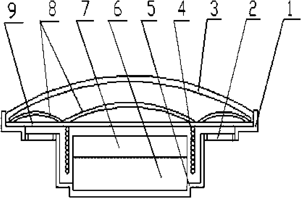
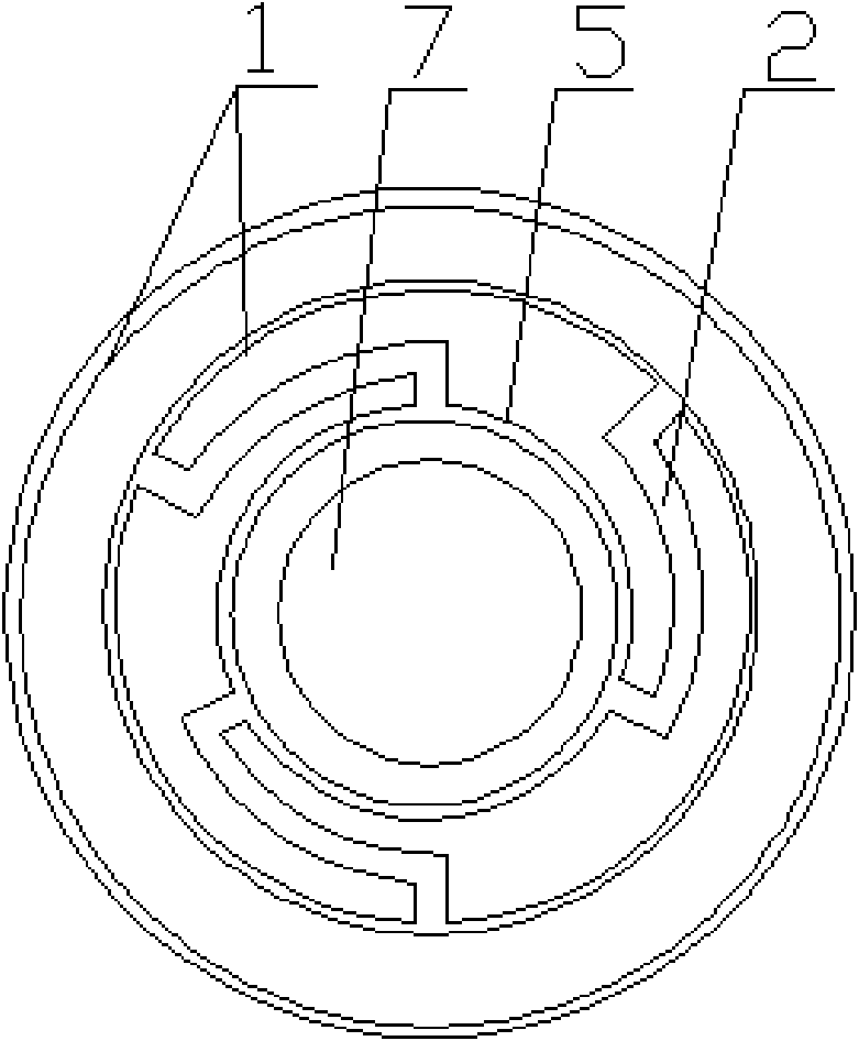
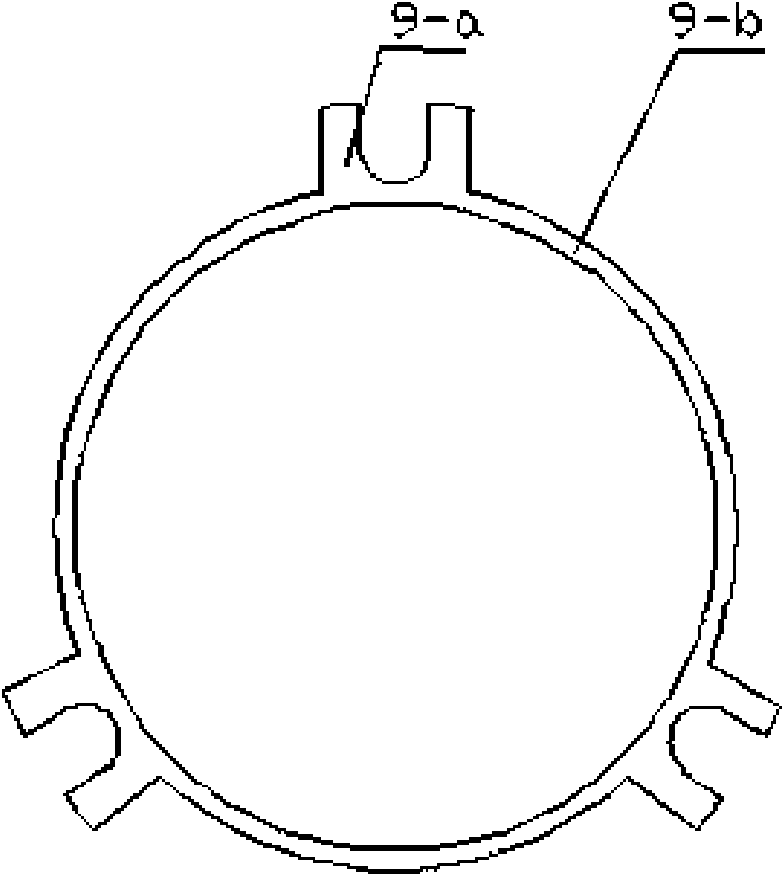
[0027] Such as figure 1 As shown, it is a cross-sectional view of the installation structure of a loudspeaker, which includes a shell assembly, a diaphragm assembly, and an upper cover 3. The upper cover 3 is located above the diaphragm assembly, and is fixedly installed on the upper shell of the shell assembly along the steps. 1 place. The housing assembly includes a step 1 along the upper edge of the housing, a yoke 5, a magnet 6, and a magnetically conductive plate 7. The magnet 6 and the magnetically conductive plate 7 are fixedly installed in the yoke 5 from the inside to the outside. The diaphragm assembly includes a shrapnel 9, a vibrating The diaphragm 8 and the coil 4, the coil 4 is fixed at the intersection of the two curved surfaces of the vibrating diaphragm 8, placed in the gap between the yoke 5, the magnet 6 and the magnetic plate 7, the vibrating diaphragm (8) and the shrapnel (9) The ring structure (9-b) is fixedly connected, and the shell assembly also inclu...

Embodiment 2

[0031] In this embodiment, the shrapnel 9 is omitted, such as Figure 5 The structure along the step 1 on the housing is shown. At this time, the outer edge of the diaphragm 8 is fixed on the inner side of the symmetrical strip hole along the step 1 on the housing.

[0032] The structure of the rest of this embodiment is the same as that of Embodiment 1.

Embodiment 3

[0034] In this embodiment, the shrapnel 9 is omitted, and the structure of the elastic structure 2 and the shell assembly adopts the following Image 6 In the structure shown, the elastic structure 2 is located at the lower part of the inner groove of the yoke 5 and is fixedly connected with the groove.

[0035] The structure of the remainder of this embodiment is the same as that of Embodiment 1

[0036] In the three embodiments described, the measured sound pressure and current relationship curves are as follows Figure 7 shown.


PUM


Abstract

The invention discloses a loudspeaker, which comprises a shell assembly, a diaphragm assembly and an upper cover. The upper cover is arranged above the diaphragm assembly; the upper cover and the diaphragm assembly are fixedly arranged inside an upper edge step of the shell; and the shell assembly comprises an upper edge step of the shell, a magnet yoke, a magnet, a magnetic conducting plate and an elastic structure which connects the upper edge step of the shell and the magnet yoke into a whole, wherein the magnet yoke has a groove structure; the magnet is arranged inside the groove; and the magnetic conducting plate is arranged above the magnet. The diaphragm assembly comprises an elastic sheet, a vibrating diaphragm and a coil, wherein the vibrating diaphragm is connected with an annular structure of the elastic sheet; and the coil is arranged at a curved surface junction of the vibrating diaphragm and is arranged inside the magnet yoke. Due to the arrangement of the elastic structure, the loudspeaker has the bone conduction characteristic, fulfills the aims of protecting the hearing of a user and producing perfect sound, and also has the advantages of simple and convenient manufacturing technology, high compatibility with conventional products, and easy replacement.

Description

technical field [0001] The invention relates to a loudspeaker, in particular to a small or micro loudspeaker with bone conduction effect. Background technique [0002] A small (or miniature) loudspeaker is all housed in the inside of existing earphones (or earphones). The built-in vibrating diaphragm of the speaker emits sound by vibrating the air under the action of the coil. In order to obtain a better sound effect, the vibrating diaphragm used in the existing earphone (or earphone) usually consists of two curved surfaces with different curvature radii. The outer curved surface with a larger radius of curvature is used for sounding in the low and middle frequency bands, while the inner curved surface with a smaller radius of curvature is used for sounding in the high frequency band. In addition, when designing the structure of earphones (or earphones), the method of closing the ear canal is usually adopted to make the air in the ear cavity resonate, so as to obtain a bett...

Claims


Application Information

Patent Timeline
Patent Type & Authority Applications(China)
IPC IPC(8): H04R9/06H04R9/02
CPCH04R7/20H04R2460/13H04R9/06
Inventor 陈奚平
Owner 陈奚平
Why Eureka
Try Eureka