Electronic compound mounting device

A technology for electronic component installation and electronic components, which is applied in the direction of electrical components, electrical components, etc., can solve the problems of inseparable electronic components and high adhesion, and achieve the effects of improving reliability, improving the accuracy of installation positions, and suppressing mistakes

Active Publication Date: 2011-01-12
JUKI CORP
View PDF6 Cites 11 Cited by
  • Summary
  • Abstract
  • Description
  • Claims
  • Application Information

AI Technical Summary

Problems solved by technology

[0005] In addition, there is a problem that the adhesiveness between some electronic components and the tip of the suction nozzle is too high, and the electronic component cannot be separated when released from the tip, and the mounting head is placed in the state where the electronic component is sucked. Move to the next destination, the so-called bring-back problem

Method used


Image

  • Electronic compound mounting device
  • Electronic compound mounting device
  • Electronic compound mounting device

Examples


Embodiment approach

[0045] based on Figure 1 to Figure 9 , to describe the embodiment of the present invention. Below, as shown in the figure,

[0046] Let two directions orthogonal to each other in the horizontal plane be an X-axis direction and a Y-axis direction, respectively.

[0047] In addition, let the vertical direction orthogonal to these be a Z-axis direction.

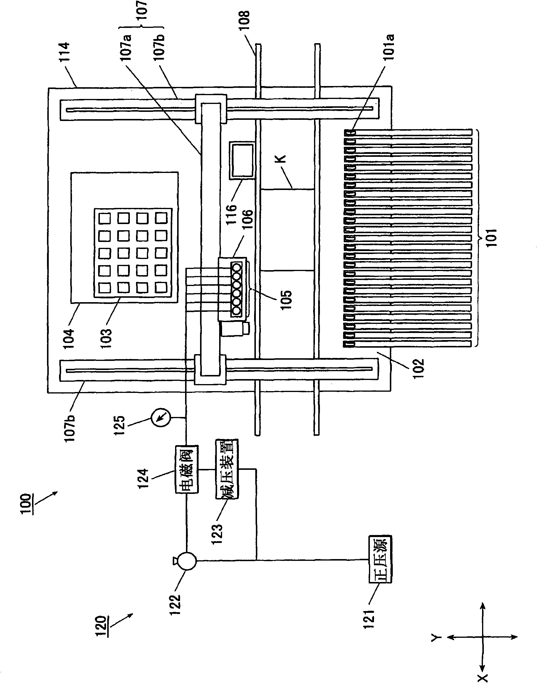
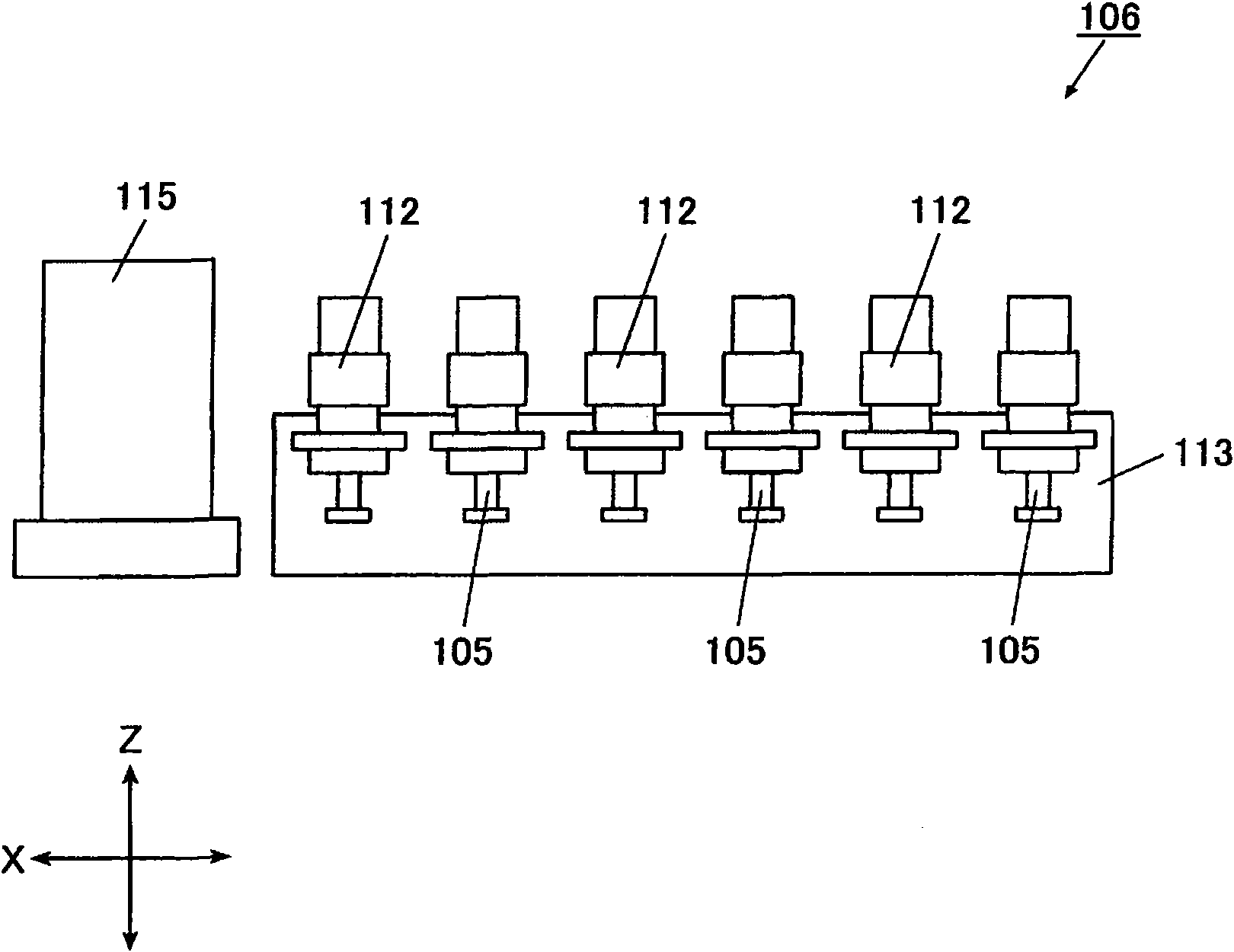
[0048] Electronic component mounting apparatus 100 such as figure 1 As shown, there are: a first component supply unit 102 that arranges and holds a plurality of electronic component feeders 101 that supply electronic components to be mounted along the X-axis direction; a second component supply unit 104 that is arranged for placing The tray 103 of various electronic components; the substrate conveying unit 108, which conveys the substrate along the X-axis direction; The electronic component loading operation of K; the loading head 106, which can lift and hold a plurality of, for example, 6 suction nozzles 105, to hold the ...


PUM


Abstract

The invention relates to an electronic compound mounting device for preventing absorption error and leading-back of electronic compounds. The electronic compound mounting device (100) is provided with: a pressure detection unit (125) detecting the inner pressure of an adsorption nozzle (105); and an acquisition control unit (30) of absorption required time, wherein the absorption action of the absorption nozzle is carried out through a negative pressure supply unit (122) in a compound supply part (102) relative to each electronic compound when mounting action control is not carried out, and the pressure detection unit measures and stores the absorption required time till the detection pressure becomes the target absorption pressure, and the absorption nozzle is raised after the absorption of each electronic compound is continuous through the negative supply unit according to the absorption required time obtained by the acquisition control unit of absorption required time when the action control unit is installed on the electronic compound.

Description

technical field [0001] The invention relates to an electronic component mounting device which uses a suction nozzle to absorb and mount electronic components. Background technique [0002] A conventional electronic component mounting device has a mounting head equipped with a suction nozzle and can move freely on the X-Y plane. By making the suction nozzle absorb the electronic component from the electronic component feeder, the mounting head is moved to the component mounting position of the substrate. The mounting position supplies positive pressure into the suction nozzle to release the electronic component, thereby mounting the electronic component. [0003] However, depending on the electronic component, the size, weight, surface material, etc. of the electronic component are different. During adsorption, air leakage (air leakage) may occur between the tip of the suction nozzle and the surface of the electronic component, and sufficient retention cannot be achieved. fo...

Claims


Application Information

Patent Timeline
Patent Type & Authority Applications(China)
IPC IPC(8): H05K13/04
Inventor 粟野元一郎
Owner JUKI CORP
Why Eureka
Try Eureka