Electromagnetic drive type flapping wing micro-aircraft

An electromagnetic drive and aircraft technology, applied in toy planes, entertainment, toys, etc., can solve the problems of small passive twist of wings, large output force, large required voltage, etc., and achieve the effect of simple control circuit and small size

Inactive Publication Date: 2011-01-19
SHANGHAI JIAO TONG UNIV
View PDF4 Cites 8 Cited by
  • Summary
  • Abstract
  • Description
  • Claims
  • Application Information

AI Technical Summary

Problems solved by technology

[0005] The present invention aims at the above-mentioned deficiencies in the prior art, and provides an electromagnetically driven flapping-wing micro-aircraft, which realizes a flapping-wing micro-aircraft with a wingspan of less than 3 cm through MEMS processing, and solves the problem of a large required voltage caused by the piezoelectric ceramic drive. It is difficult to carry power by itself, and the passive rotation of the wings is small. The electromagnetic driver obtains the driving force by using the current-carrying conductor to be stressed in the magnetic field. It is directly driven by the electromagnetic force. It has a simple structure, convenient and flexible control, and a large output force.

Method used


Image

  • Electromagnetic drive type flapping wing micro-aircraft
  • Electromagnetic drive type flapping wing micro-aircraft
  • Electromagnetic drive type flapping wing micro-aircraft

Examples


Embodiment Construction

[0027] The embodiments of the present invention are described in detail below. This embodiment is implemented on the premise of the technical solution of the present invention, and detailed implementation methods and specific operating procedures are provided, but the protection scope of the present invention is not limited to the following implementation example.

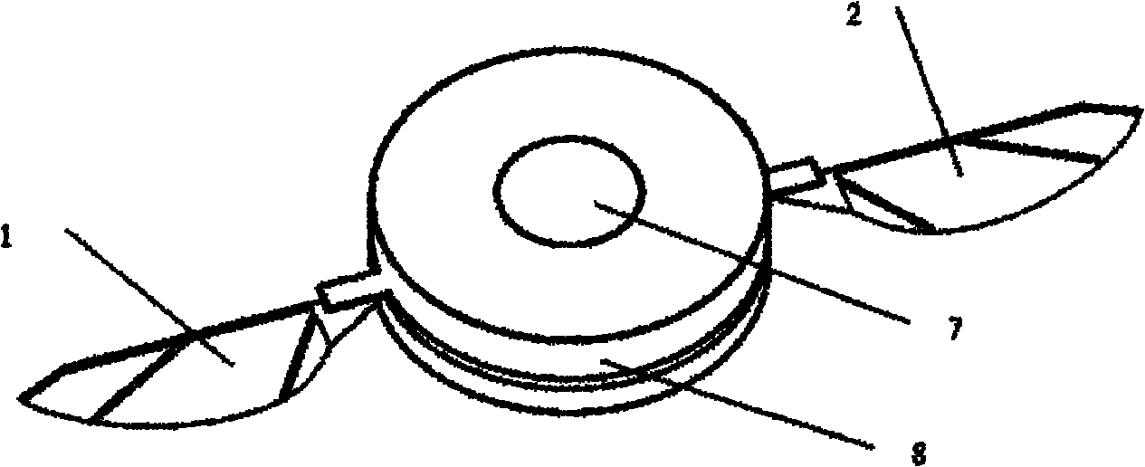
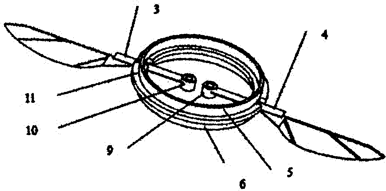
[0028] Such as figure 1 and figure 2 Shown, this embodiment comprises: a pair of left wing 1 and right wing 2 and its corresponding first carapace 3 and second carapace 4 and annular permanent magnet 5,6, control chip 7, casing 8, two the first carapace A helical coil 9, a second helical coil 10 and a chest cavity 11, wherein: a pair of left wings 1 and right wings 2 are bonded to one end of the first carapace 3 and the second carapace 4 respectively, the first carapace 3 and the second carapace 4 The other end of the second carapace 4 is bonded with the first helical coil 9 and the second helical coil 10 respec...


PUM


Abstract

The invention relates to an electromagnetic drive type flapping wing micro-aircraft in the technical field of micro-aircrafts, which comprises a pair of wings and corresponding carapaces thereof, annular permanent magnets, a control chip, a shell, two spiral coils as well as a thoracic cavity, wherein the pair of wings are respectively bonded to one ends of respective carapaces, and the spiral coils are respectively bonded to the other ends of the carapaces; the two annular permanent magnets are respectively fixed to the upper side and the lower side of the thoracic cavity; the control chip is bonded to the center of the top of the shell and connected with the spiral coils; and the shell is fixed to the outer edge of the thoracic cavity. The invention realizes the flapping wing micro-aircraft with the wingspan of smaller than 3cm by processing through an MEMS (Micro-electromechanical System) process, obtains driving force by utilizing the stress of a power-on conductor in a magnetic field, is directly driven by electromagnetic force and has the advantages of simple structure, convenient and flexible control and strong output force.

Description

technical field [0001] The invention relates to a device in the technical field of micro-aircraft, in particular to an electromagnetic-driven flapping-wing micro-aircraft. Background technique [0002] The flapping-wing micro-aircraft is a micro-aircraft that imitates the flight of birds or insects. In recent years, with the development of cutting-edge technologies such as military and MEMS, the use of winged micro-aircraft (FMAV) has gradually become a research hotspot in the scientific and technological circles. Micro air vehicle is a new type of aircraft developed in the 1990s. The U.S. Defense Advanced Research Projects Agency proposed the basic indicators of micro-aircraft: the size of the aircraft is less than 15cm, the weight is between 10g and 100g, the flight time is 20-60min, and the flight speed is 25-70km / h. Micro air vehicles have the advantages of small size, light weight, good maneuverability and aerodynamic performance, and have very broad application prosp...

Claims


Application Information

Patent Timeline
Patent Type & Authority Applications(China)
IPC IPC(8): A63H27/28
Inventor 张卫平孟坤迟鹏程陈文元李洪谊崔峰吴校生刘武
Owner SHANGHAI JIAO TONG UNIV
Why Eureka
Try Eureka