Server physical position marking method, equipment and system
A technology of physical location and marking equipment, applied in the field of network communication, can solve the problems of heavy workload and high cost, and achieve the effect of improving the success rate, reducing the cost and workload, and reducing the error rate
- Summary
- Abstract
- Description
- Claims
- Application Information
AI Technical Summary
Problems solved by technology
Method used
Image

Examples
Embodiment 1
[0034] figure 1 It is a flowchart of a method for marking a server's physical location according to Embodiment 1 of the present invention. The executive body of this embodiment is a switch configured at the top of the rack, such as figure 1 As shown, the marking method of the present embodiment includes:
[0035] Step 101, the switch receives the configuration request sent by the server;
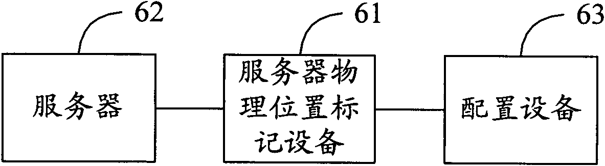
[0036]Among them, in the "zero-touch" configuration and deployment scheme, after the server is installed at a designated location and powered on, it will broadcast a configuration request to the configuration device installed with automated operation and maintenance management software to configure and deploy it. Wherein, the specified location is specifically on a rack in a certain group of a certain cluster. Since the server is connected to the data center network through the switch, the switch will first receive the configuration request from the server.
[0037] Step 102, the switch ...
Embodiment 2
[0048] figure 2 It is a flow chart of the method for configuring the physical location information of the switch provided by Embodiment 2 of the present invention. Such as figure 2 As shown, the configuration process of this embodiment includes:
[0049] Step 201, making a configuration package of the physical location information of the switch;
[0050] Among them, the configuration package in this embodiment mainly refers to an external storage device used to store the physical location information of the switch, which can be a barcode scanner, a digital punch on the rack, a U disk, a flash memory card, an electronically erasable Electrically Erasable Programmable Read-Only Memory (EEPROM for short) or Static Random Access Memory (SRAM for short) and any carrier capable of storing electronic marks. In this embodiment, a USB flash drive is taken as an external storage device as an example.
[0051] Specifically, the process of making the configuration package includes: ...
Embodiment 3
[0066] image 3 It is a flow chart of the method for configuring and deploying servers provided by Embodiment 3 of the present invention. This embodiment is implemented based on Embodiment 1 and Embodiment 2, and the same operations are not described again. Such as image 3 As shown, the method of the present embodiment includes:
[0067] Step 301, making a configuration package of the switch in advance, and fastening the configuration package to the rack where the switch is located;
[0068] In step 302, the switch configures its own physical location information in advance according to the information in the configuration package; for the above steps 301 and 302, refer to the description in Embodiment 2 for details.
[0069] Step 303, the server connected to the switch sends a DHCP message to the DHCP server in the data center through the switch, requesting configuration and deployment;
[0070] Step 304, the switch receives the DHCP message through the port connected to...
PUM
 Abstract
Description
Claims
Application Information
 - Generate Ideas
- Intellectual Property
- Life Sciences
- Materials
- Tech Scout
- Unparalleled Data Quality
- Higher Quality Content
- 60% Fewer Hallucinations
Browse by: Latest US Patents, China's latest patents, Technical Efficacy Thesaurus, Application Domain, Technology Topic, Popular Technical Reports.
© 2025 PatSnap. All rights reserved.Legal|Privacy policy|Modern Slavery Act Transparency Statement|Sitemap|About US| Contact US: help@patsnap.com