Clamping element

A technology of clamping parts and clamping, which is applied in the direction of clamps, manufacturing tools, etc., can solve the problems of large structural size, unsatisfactory stability and other problems of interference edge failure hidden dangers, and achieve high stability

Inactive Publication Date: 2013-07-24
VEL VEGA DESIGN E TECHA IND UNIP LDA
View PDF0 Cites 0 Cited by
  • Summary
  • Abstract
  • Description
  • Claims
  • Application Information

AI Technical Summary

Problems solved by technology

[0004] However, such a clamping part with a pair of webs has an unsatisfactory stability, especially with respect to lateral forces, ie forces acting in the direction of the pivot axis of the webs
In addition, the use of such deflecting webs leads to numerous weakening points on the deflecting axis, since chips can get between the parts of the clamping part and prevent satisfactory functioning
Further disadvantages of such a clamping part with web pairs are the presence of numerous interfering edges and the attendant risk of failure as well as the relatively large structural dimensions of such a clamping part

Method used


Image

  • Clamping element
  • Clamping element
  • Clamping element

Examples


Embodiment Construction

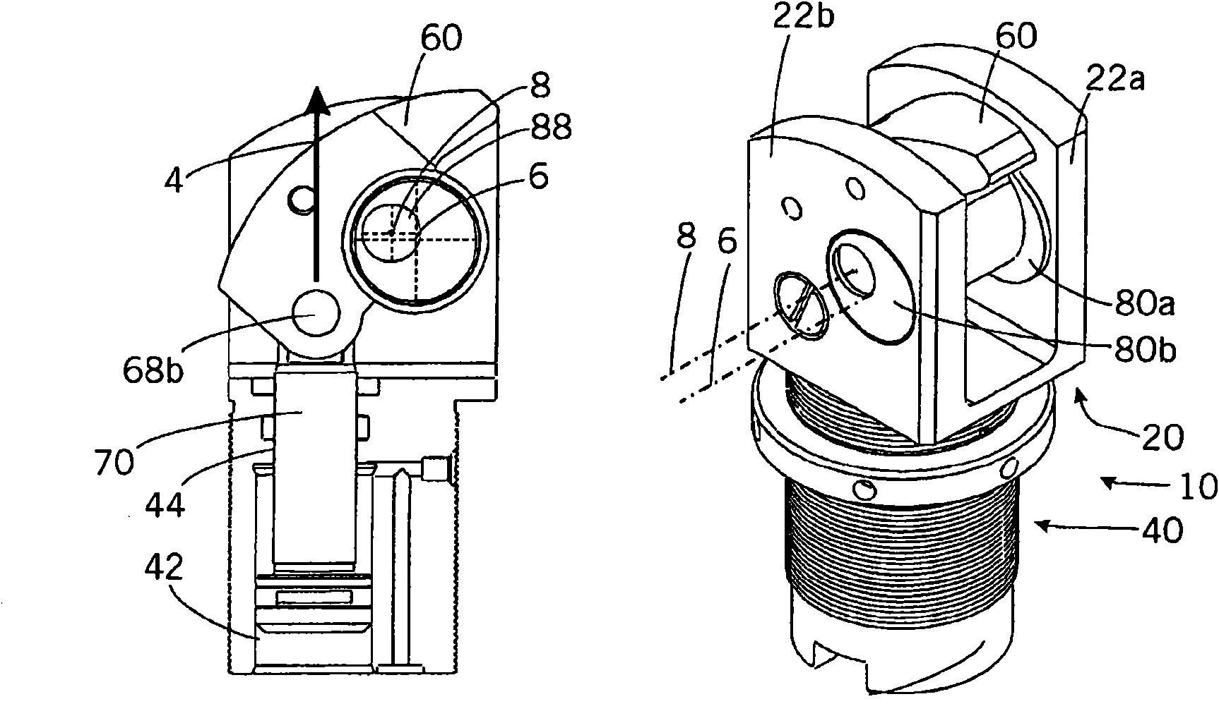
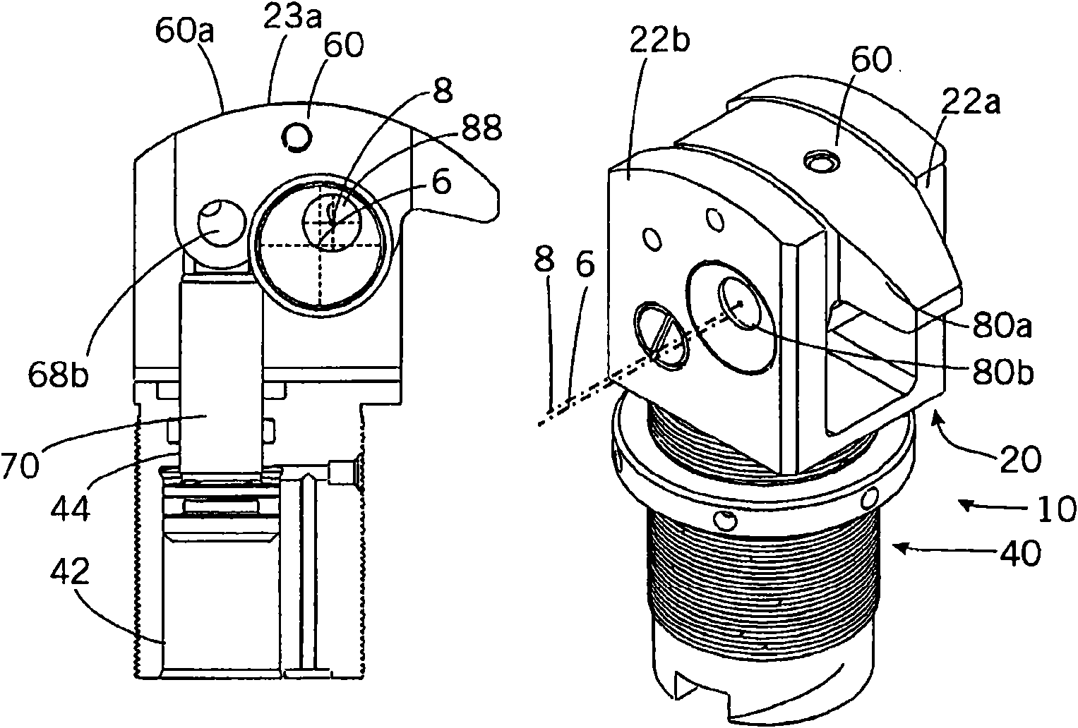
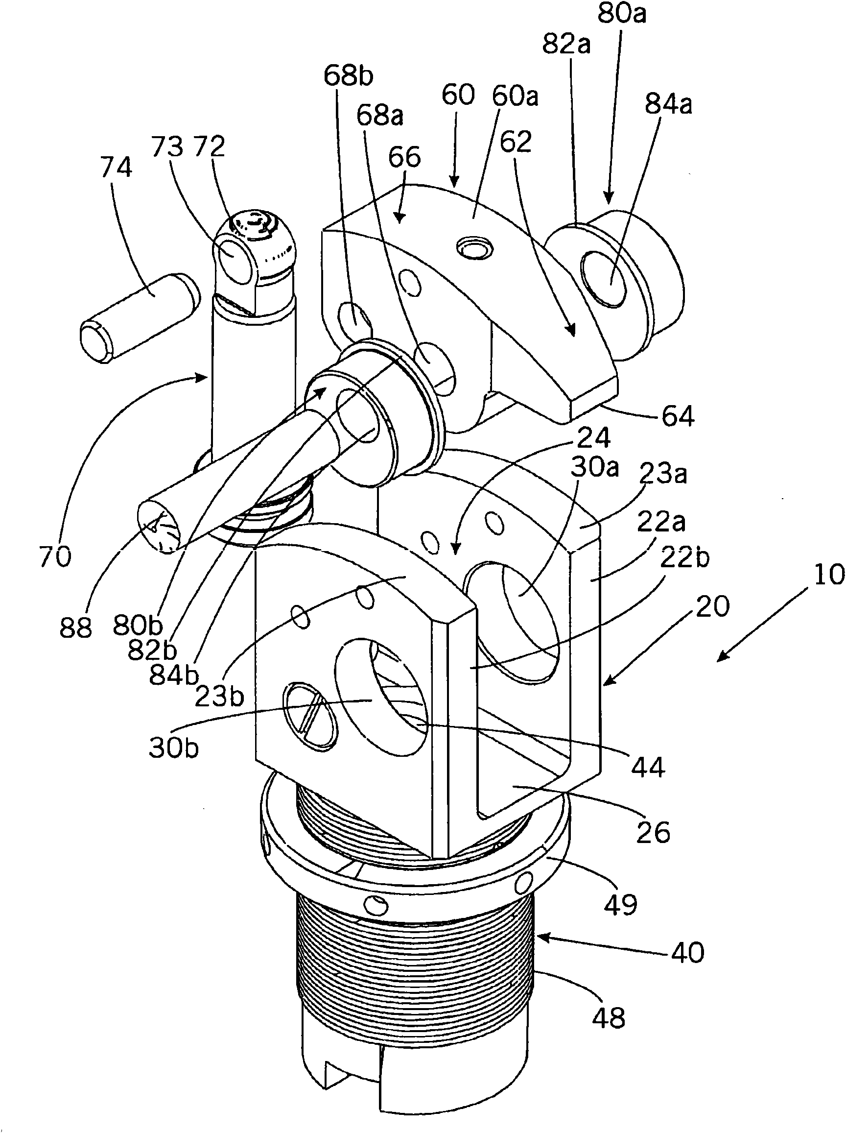
[0031] Figure 1a , 1b and 2 show a first embodiment of the clamping part and its individual components according to the invention.

[0032] by means of figure 2 as well as Figure 1a explain first Figure 1a , The various components of the embodiments of 1b and 2 and the connection of various components.

[0033] The clamping part has a housing 10 with a U-shaped fork section 20 and a cylindrical fastening section 40 connected thereto. The fork section 20 has two planar fork shoulders 22 a , 22 b which are arranged parallel to one another and laterally delimit a free space 24 located therebetween. The prong shoulders 22a, 22b are integrally formed on the base plate 26 at their lower ends. From this base plate 26 extends downward a cylindrical fixing section 40 . as Figure 1a As can be seen in the cross-sectional view of FIG. 1 , a cylinder bore 42 is provided in this fastening section, which serves to accommodate a piston 70 which will be described later. Concentrically...


PUM


Abstract

The invention relates to a clamping element for fixing a workpiece, comprising a housing (10) that is fixed during operation, a clamping lever (60) that can be moved relative to the housing (10) and has a clamping region (64) for subjecting the workpiece to a force as well as a piston (70) that can be deployed in a translatory manner relative to the housing (10) in a deployment direction (4). The invention is characterized in that the piston (70) is designed for pivoting the clamping lever (60) so that the clamping lever (60) can be moved between a released initial state (60) and a clamped final state. According to the invention, the clamping lever (60) is mounted to the housing (10) or the piston by at least one eccentric disk (80a, 80b). The clamping element according to the invention allows for a compact and stable design.

Description

technical field [0001] The invention relates to a clamping part for fastening a workpiece, which has a fixed housing during operation, a clamping lever (with a clamping point for force-loading the workpiece) which is movable relative to the housing and which can be moved relative to the housing The piston moved out is translated in the outward direction, wherein the piston is designed to deflect the clamping lever, so that the clamping lever is movable between a released initial position and a clamped end state. Background technique [0002] Such clamping elements are known from the prior art. They are used to securely clamp the workpiece on the clamping surface. For direct contact with the workpiece, a clamping lever is provided which is movable relative to the housing and which can be deflected by the piston being pushed out in such a way that the clamping point comes into contact with the workpiece and the workpiece presses against the clamping surface with clamping forc...

Claims


Application Information

Patent Timeline
Patent Type & Authority Patents(China)
IPC IPC(8): B25B5/06
CPCB25B5/064
Inventor M·费希尔
Owner VEL VEGA DESIGN E TECHA IND UNIP LDA
Why Eureka
Try Eureka