Friction compression joint method

A technology of friction crimping and joint surface, which is applied in the field of friction crimping and can solve problems such as poor stability

Inactive Publication Date: 2011-02-02
NAKAMURATOME SEIMITSU IND
View PDF5 Cites 16 Cited by
  • Summary
  • Abstract
  • Description
  • Claims
  • Application Information

AI Technical Summary

Problems solved by technology

[0004] However, in the method using torque control, when the control is divided into tilting pressurization (friction pressurization) and upsetting pressurization (joint pressurization), the stability is poor, and there are limitations in suppressing unstable joint quality.

Method used


Image

  • Friction compression joint method
  • Friction compression joint method
  • Friction compression joint method

Examples


Embodiment Construction

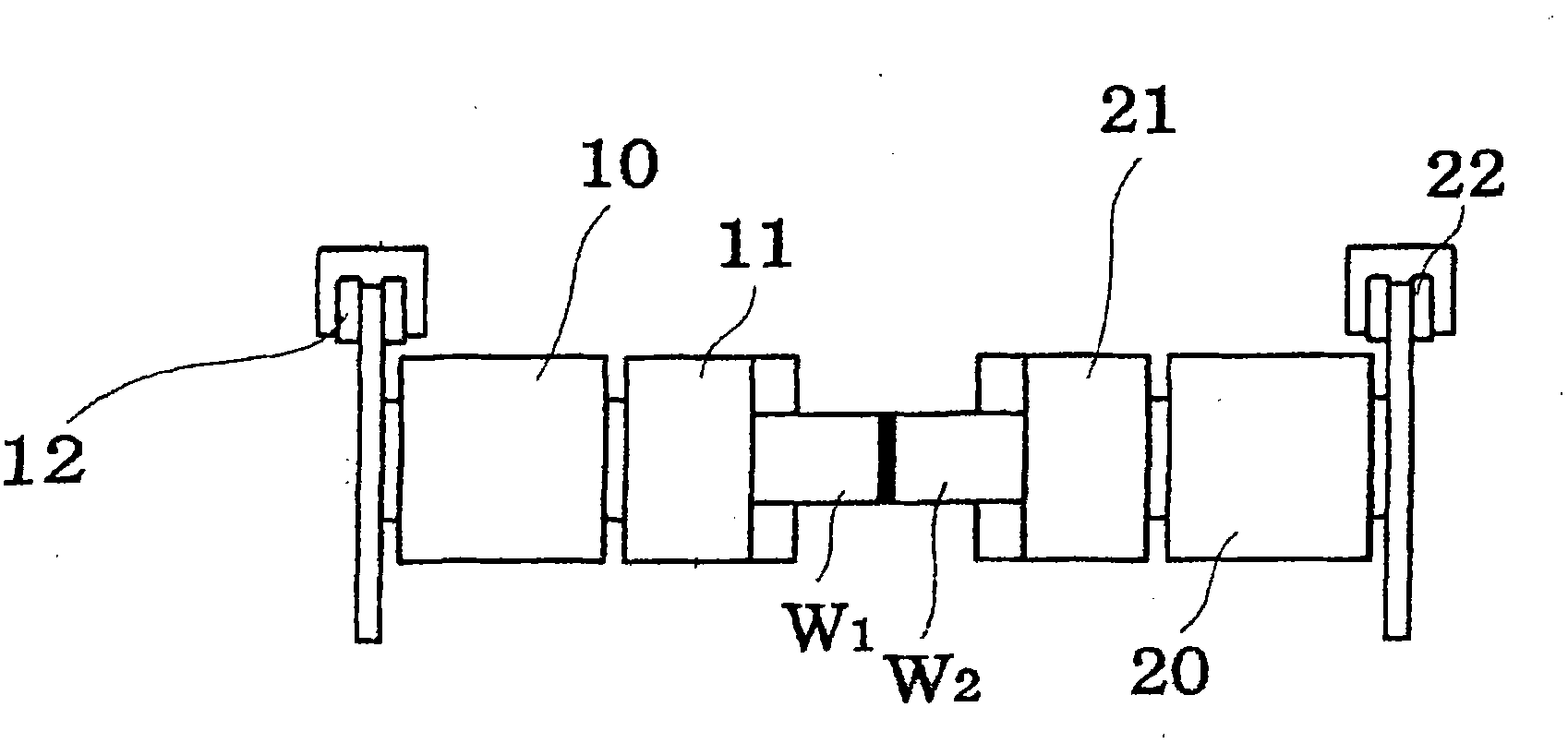
[0025] according to figure 1 The friction welding device will be described with Fig. 2(a), (b), (c).

[0026] In this embodiment, the R-side chuck, which is rotationally driven and controlled by the main shaft R20, is provided opposite to the L-side chuck 11 that is rotationally driven and controlled by the main shaft L10 in such a manner that the main axis is consistent. The side can also be a clamping device whose feed is controlled.

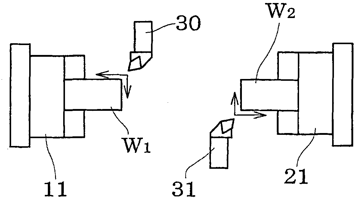
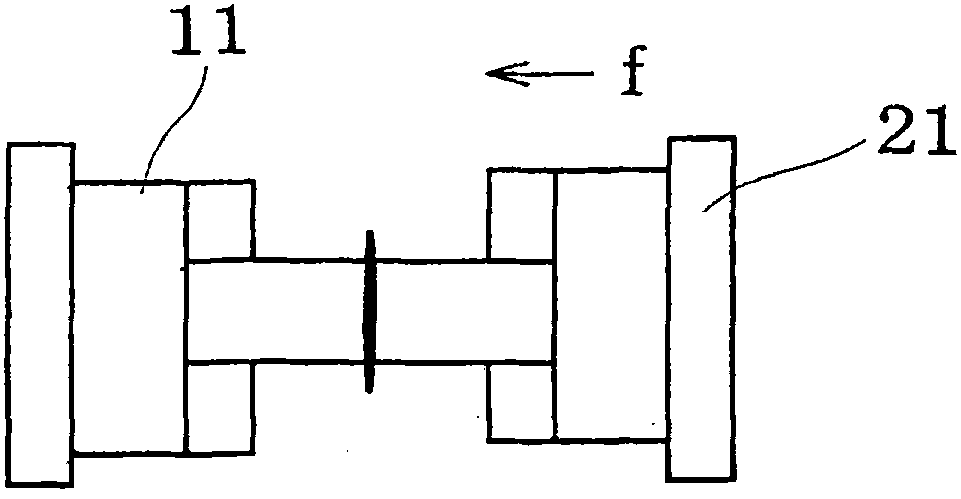
[0027] In this way, when the spindles L and R are arranged in opposite directions, the workpiece W 1 Clamped on spindle L, workpiece W 2 Clamped on the spindle R, as shown in Figure 2 (a), use turning tools 30, 31 to the workpiece W 1 , W 2 The outer diameter and the joint surface of the machine are processed, and friction welding can be performed as shown in Figure 2(b).

[0028] In addition, by providing a tool table in addition to the opposed two spindles, it is possible to remove burrs after crimping as shown in FIG. 2(c).

[0029] In addition, br...


PUM


Abstract

The invention provides a friction compression joint method capable of performing stable declining compression and upset-forging compression and easily performing the phase alignment between the workpieces. The method for friction compression joint of two workpieces (W1,W2) is characterized in that: the workpiece (W1) at one side is mounted and clamped on a main axle (L) rotation and driving under control and the workpiece (W2) at another side is mounted and clamped on another opposite main axle (R) or a clamping device (R) to make joint surfaces opposite with each other. The main axle (L) rotates, thus the joint surface of the workpiece (W1) and the joint surface of the workpiece (W2) heat by friction and contact with each other to rotate. In order to arrive at the object coordination of the inclined side pressure along the Z axle direction, the opposite main axle (R) or the clamping device (R) is subject to movement control and secondly in order to arrive at the object coordination of the upset forging pressure, the main axle (R) or the clamping device (R) is subject to movement control.

Description

Technical field [0001] The present invention relates to a method for joining workpieces by frictional compression, which is effective for obtaining stable pressurizing force and opposite phase of joining surfaces. Background technique [0002] The technique of generating rotational friction on the joint surfaces of the workpieces, and performing solid-phase pressure welding using the heat generated by the friction is well known. However, this technology applies a large pressing force between the workpieces after heating the joint surface to locally melt and soften, so the joint quality is likely to be unstable. [0003] In the prior art, in order to improve the joint quality, most of the output torque is used to control the rotation of the spindle or the movement of the clamp. [0004] However, the method using torque control is divided into tilting pressure (friction pressure) and upset pressure (joining pressure) for control with poor stability, and has limitations in suppressing ...

Claims


Application Information

Patent Timeline
Patent Type & Authority Applications(China)
IPC IPC(8): B23K20/12
CPCB23K20/1205B23K20/121B23K20/125B23K20/126
Inventor 荒井智则
Owner NAKAMURATOME SEIMITSU IND
Why Eureka
Try Eureka