Covered rotary tool and manufacturing method therefor
一种工具、覆层的技术,应用在摩擦搅拌焊接工具及其制造领域,能够解决工件亲和力低等问题,达到优异耐磨性和耐碎裂性、稳定接合质量、优异抗粘着性的效果
- Summary
- Abstract
- Description
- Claims
- Application Information
AI Technical Summary
Problems solved by technology
Method used
Image

Examples
Embodiment 1-14
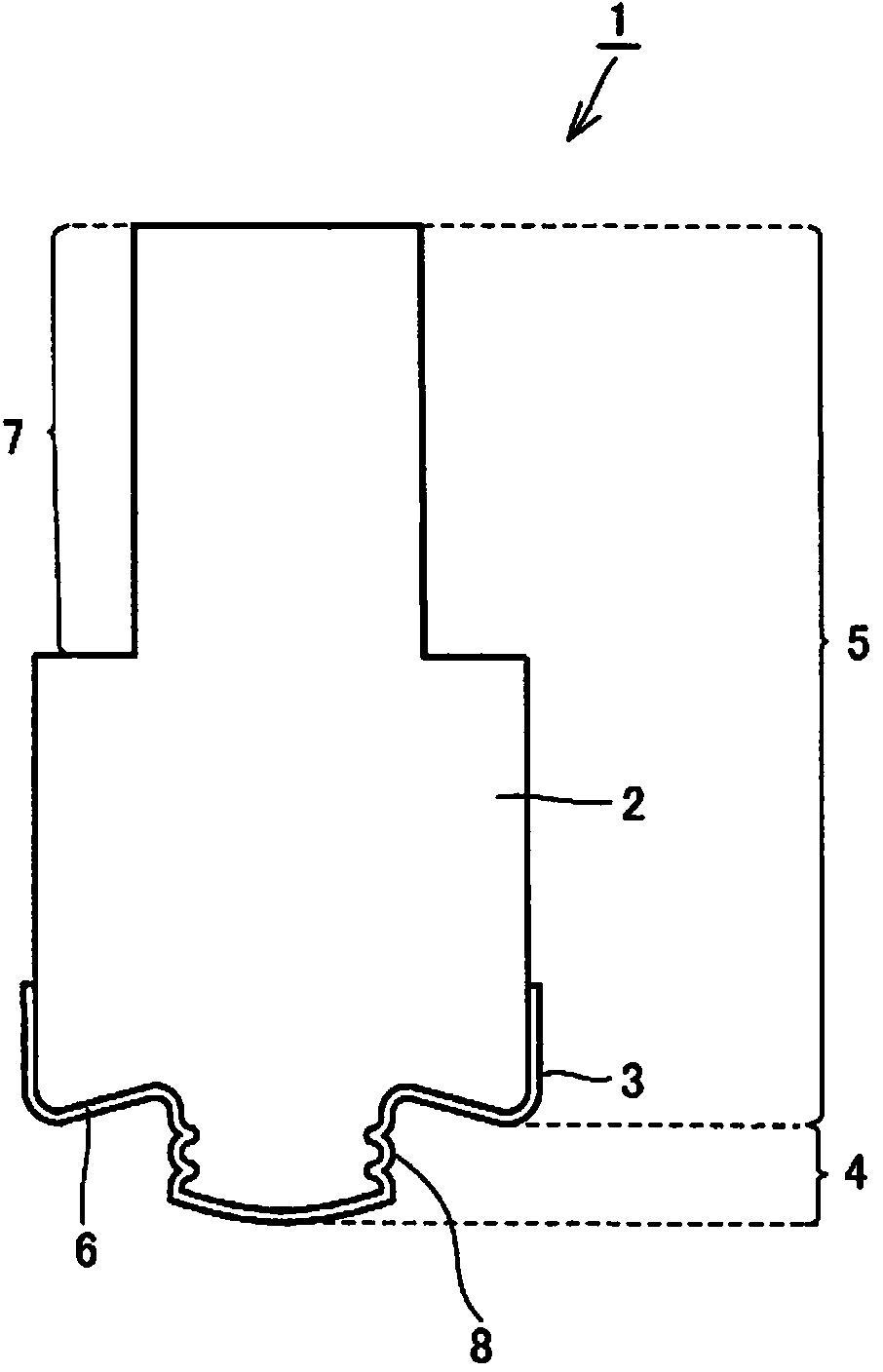
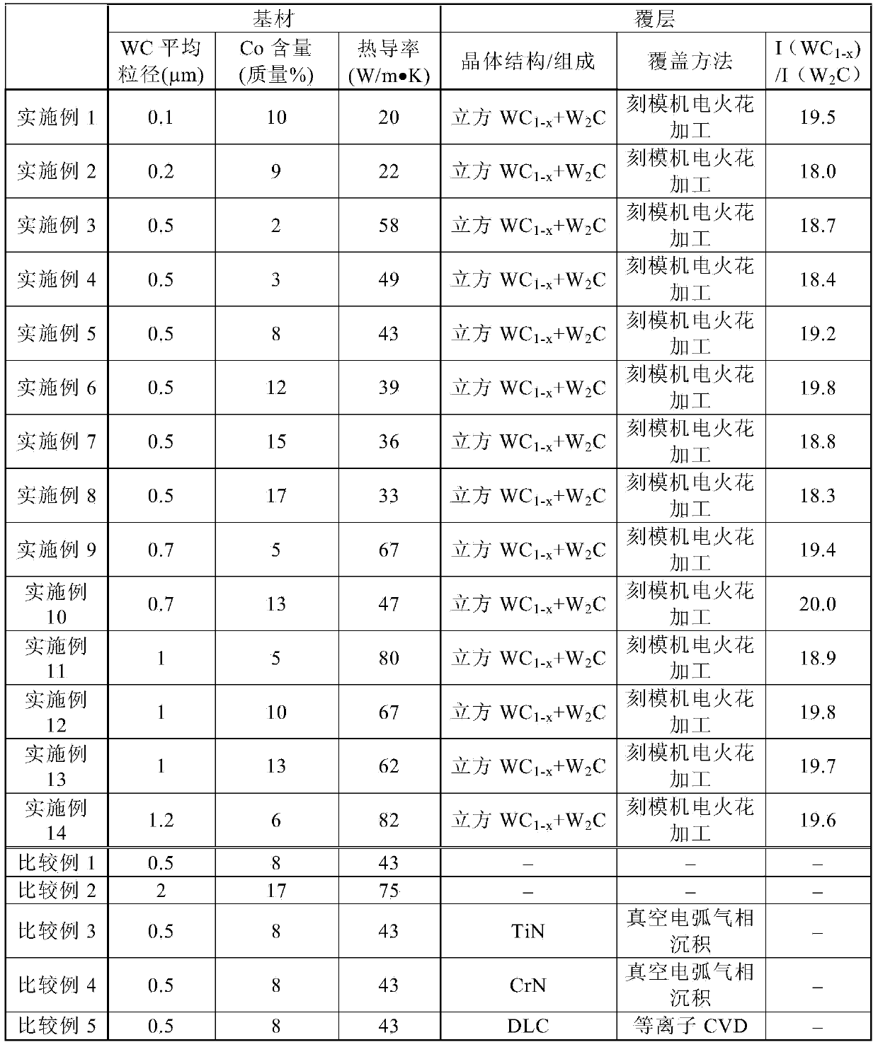
[0063] For each of Examples 1 to 14, manufactures such as figure 1 Friction stir welding tool shown. First, for the base material, a cemented carbide having the characteristics of "WC average particle size", "Co content" and "thermal conductivity" as shown in Table 1 below was prepared. The cemented carbide was ground and EDMed (the EDM conditions were adjusted in such a way that the discharge time, rest time and current peak value were adjusted so that the machining rate was 0.01 g / min) to form like figure 1 Substrate 2 of the shape shown. The substrate 2 comprises a substantially cylindrical cylindrical portion 5 with a diameter of 10 mm, and a probe portion 4 coaxial with the cylindrical portion 5 and protruding from the center of a shoulder 6 of the cylindrical portion 5 . The length from the shoulder 6 to the front end of the probe part 4 is 1.5 mm. On the side of the probe part 4, a threaded part 8 is formed, specifically, the threaded part 8 is a helical thread (M4)...
Embodiment 15 to 21
[0115] The conditions of electric discharge machining were changed to manufacture friction stir welding tools having different surface roughness Ra of the coating. Except that the conditions of electric discharge machining were changed, the same manufacturing method as in Example 5 was used (the conditions of electric discharge machining were adjusted in the following manner: adjusting discharge time, intermittent time and current peak value, so that the processing rate was 0.005g / min to 0.01g / min).
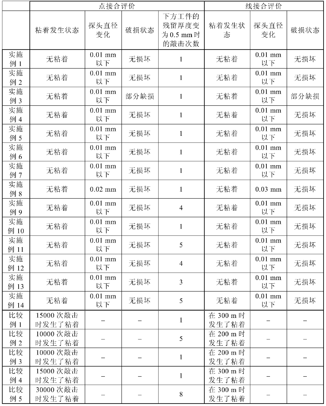
[0116] For these tools, a point bonding test and a wire bonding test were performed in a similar manner to Examples 1 to 14. The results are shown in Table 3 (the results of the point bond test are shown under "Point bond evaluation", the results of the wire bond test are shown under "Wire bond evaluation"). Table 3 also shows the results of Example 5. As for Examples 20 to 21, the evaluation was stopped when sticking occurred, and the change in probe diameter was measured afte...
PUM
| Property | Measurement | Unit |
|---|---|---|
| thermal conductivity | aaaaa | aaaaa |
| particle diameter | aaaaa | aaaaa |
| roughness | aaaaa | aaaaa |
Abstract
Description
Claims
Application Information
 - R&D
- Intellectual Property
- Life Sciences
- Materials
- Tech Scout
- Unparalleled Data Quality
- Higher Quality Content
- 60% Fewer Hallucinations
Browse by: Latest US Patents, China's latest patents, Technical Efficacy Thesaurus, Application Domain, Technology Topic, Popular Technical Reports.
© 2025 PatSnap. All rights reserved.Legal|Privacy policy|Modern Slavery Act Transparency Statement|Sitemap|About US| Contact US: help@patsnap.com