
Stacking machine and lifting appliance thereof

A spreader and main body technology, applied in the direction of lifting devices, etc., can solve the problems of affecting operators and low efficiency of stacking operations, and achieve the effect of eliminating the forward tilt angle, improving the efficiency of stacking operations, and ensuring the levelness

Inactive Publication Date: 2012-12-05
SANY GRP
View PDF0 Cites 1 Cited by
  • Summary
  • Abstract
  • Description
  • Claims
  • Application Information

AI Technical Summary

Problems solved by technology

[0004] The purpose of the present invention is to provide a stacker and its spreader to solve the problem of low stacking operation efficiency caused by the influence of the position judgment of the operator due to the forward tilt angle formed by the container in the process of hoisting the container by the stacker in the prior art

Method used


Image

  • Stacking machine and lifting appliance thereof
  • Stacking machine and lifting appliance thereof
  • Stacking machine and lifting appliance thereof

Examples


Embodiment Construction

[0022] It should be noted that the embodiments in this application and the features in the embodiments can be combined with each other if there is no conflict. Hereinafter, the present invention will be described in detail with reference to the drawings and in conjunction with the embodiments.

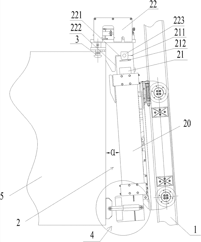
[0023] See Figure 1 to Figure 5 , Shows the structure of a spreader according to the present invention and a stacker with the spreader. As shown in the figure, the stacker according to the present invention includes a mast 1 and a spreader 2.

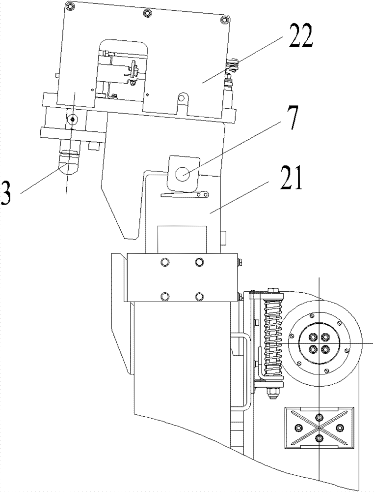
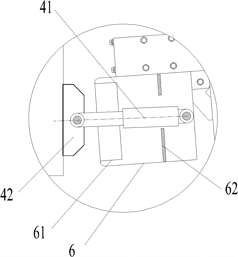
[0024] Among them, the mast (same as the spreader bracket) 1 is usually installed longitudinally in front of the driver's cab of the stacker, and moves with the stacker body. The spreader 2 includes: a spreader main body 20, which cooperates with the mast 1 and can move longitudinally along the mast 1; a spreader head 22, the first end is hinged to the upper end of the spreader main body 20, and the second end is provided for connecting the contain...


PUM


Abstract

The invention provides a lifting appliance which comprises a lifting appliance main body and a lifting appliance head part arranged at the upper end of the lifting appliance main body, wherein the lifting appliance main body can longitudinally move along a lifting appliance bracket, the first end of the lifting appliance head part is hinged with the upper end of the lifting appliance main body and the second end thereof is connected with a container through a lock head; and the lifting appliance also comprises an angle compensating mechanism, wherein one end of the angle compensating mechanism is connected to the lifting appliance main body and the other end thereof is used for connecting with the container connected to the lock head, and the container drives the lifting appliance head part to rotate for regulating the top rake of the container by forwards driving the container. The invention also provides a stacking machine which comprises the lifting appliance. According to the stacking machine of the invention, the difficulty of stacking operation of operators is lowered, and the effect of improving the stacking operation efficiency and the stacking operation precision is achieved.

Description

Technical field [0001] The invention relates to the field of hoisting machinery, and more specifically, to a stacker and its sling. Background technique [0002] The prior art stacker includes a vehicle body, a door frame arranged on the front side of the vehicle body, and a spreader that can move longitudinally along the door frame, wherein the spreader has a twist lock to connect with the container. When the container is installed on the spreader, the movement of the spreader along the gantry drives the container to move longitudinally, thereby achieving the function of stacking or unloading the container. [0003] The inventor found that in the process of lifting the container and placing the container in the spreader of the above-mentioned stacker, the door frame mostly has a forward tilting action, plus the bending deformation of the door frame and the spreader caused by the spreader and the weight of the container , So that the container has a certain angle of forward inclin...

Claims


Application Information

Patent Timeline
Patent Type & Authority Patents(China)
IPC IPC(8): B66F9/12B66F9/22B66F9/07
Inventor 冯高廖荣华李翠英
Owner SANY GRP
Learn More