
Grinding machine with laser positioning function and control method of grinding machine

A technology of laser positioning and grinding machine, which is applied in the control of workpiece feed movement, grinding frame, machine tool suitable for grinding workpiece plane, etc. It can solve the problems of unevenness, uneven ground parallelism and uneven grinding

Active Publication Date: 2016-06-15
JINJIANG XINGYI POLISHING MACHINERY
View PDF7 Cites 9 Cited by
  • Summary
  • Abstract
  • Description
  • Claims
  • Application Information

AI Technical Summary

Problems solved by technology

[0002] Existing grinding machines have been widely used in polishing and grinding stone floors, cement floors and hard floors, but now the ground has different parallelism and some unevenness, and if there is a slope or angle slope at a certain angle, it will cause The grind is uneven and needs to be re-grinded

Method used


Image

  • Grinding machine with laser positioning function and control method of grinding machine
  • Grinding machine with laser positioning function and control method of grinding machine

Examples


Embodiment Construction

[0022] The present invention will be further described below in conjunction with the accompanying drawings and specific embodiments.

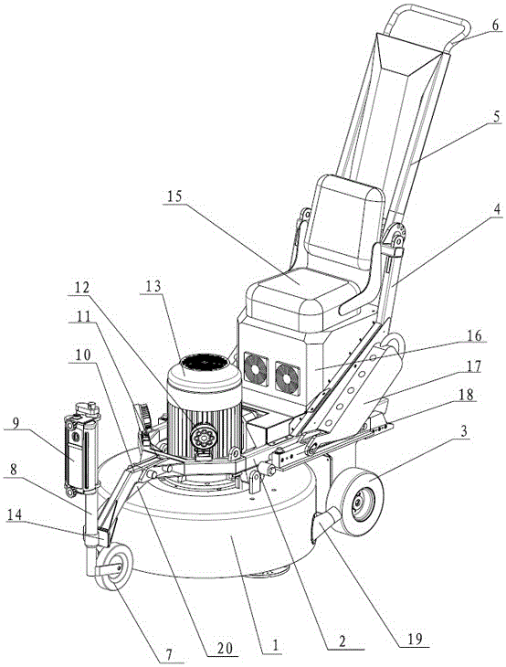
[0023] Such as Figure 1~2 As shown, a grinding machine with laser positioning includes a grinding assembly and a frame, and the grinding assembly includes a grinding base 1, a motor 13 arranged on the grinding base 1, and several grinding discs built into the grinding base 1, The grinding disc is connected with the output shaft of the motor 13 through a gear drive assembly, and the gear drive assembly is arranged in the grinding base 1; the grinding base 1 is arranged on the frame; the machine The frame includes a horizontal support frame 2, a slanting rod 4 arranged obliquely at the rear end of the supporting frame 2, a swing rod 5 rotatably connected to the slanting rod 4, and a push handle 6 arranged at the top of the swing rod 5; the grinding base 1. It is arranged at the bottom of the front end of the support frame 2 and is connected to ...


PUM


Abstract

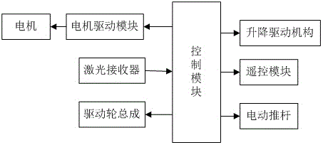
The invention relates to a grinding machine with a laser positioning function and a control method of the grinding machine. The grinding machine comprises a grinding assembly and a rack; the grinding assembly is arranged on the rack; a grinding base is arranged at the bottom of the front end of a supporting frame and is connected with the supporting frame through a lifting driving mechanism; the two sides of the bottom portion of the rear end of a supporting rod are each provided with a rear wheel, and the rear wheels are driven through a driving wheel assembly; a universal wheel is arranged at the front end of the supporting rod and is fixedly connected with the front end of the supporting frame through a front support; an electric push rod for controlling the universal wheel to ascend and descend is further arranged on the universal wheel, and a pushing rod of the electric push rod is fixedly connected with the universal wheel; and a laser receiver is further arranged at the front end of the electric push rod, and the laser receiver, a motor, the lifting drive mechanism, the electric push rod and the driving wheel assembly are all electrically connected with a control module. The grinding machine has the beneficial effects that the grinding height is controlled through the laser receiver, and it is ensured that the parallelism degree of a grinding plane is consistent.

Description

technical field [0001] The invention relates to the field of grinding, in particular to a grinding machine with laser positioning and a control method thereof. Background technique [0002] Existing grinding machines have been widely used in polishing and grinding stone floors, cement floors and hard floors, but now the ground has different parallelism and some unevenness, and if there is a slope or angle slope at a certain angle, it will cause The grind is uneven and needs to be re-grinded. Contents of the invention [0003] The object of the present invention is to address the above deficiencies and provide a grinding machine with laser positioning and its control method. The grinding height is controlled by the laser receiver to ensure that the parallelism of the grinding plane is consistent. [0004] The solution adopted by the present invention to solve the technical problem is a grinding machine with laser positioning, including a grinding assembly and a frame. The ...

Claims


Application Information

Patent Timeline
Patent Type & Authority Applications(China)
IPC IPC(8): B24B7/18B24B27/00B24B55/10B24B49/12B24B41/02
CPCB24B7/186B24B27/0076B24B41/02B24B49/12B24B55/102
Inventor 谢其鹏
Owner JINJIANG XINGYI POLISHING MACHINERY
Learn More