Electrical apparatus such as a switch

A technology of electrical equipment and electrical connection, applied in the parts of flip switches/rocker switches, contact vibration/shock damping, etc., to achieve the effect of reducing noise and smooth operation

Inactive Publication Date: 2011-02-09
LEGRAND SNC
View PDF7 Cites 5 Cited by
  • Summary
  • Abstract
  • Description
  • Claims
  • Application Information

AI Technical Summary

Problems solved by technology

This therefore results in louder or weaker noises that are rapidly transmitted to other parts of the device

Method used


Image

  • Electrical apparatus such as a switch
  • Electrical apparatus such as a switch
  • Electrical apparatus such as a switch

Examples


Embodiment Construction

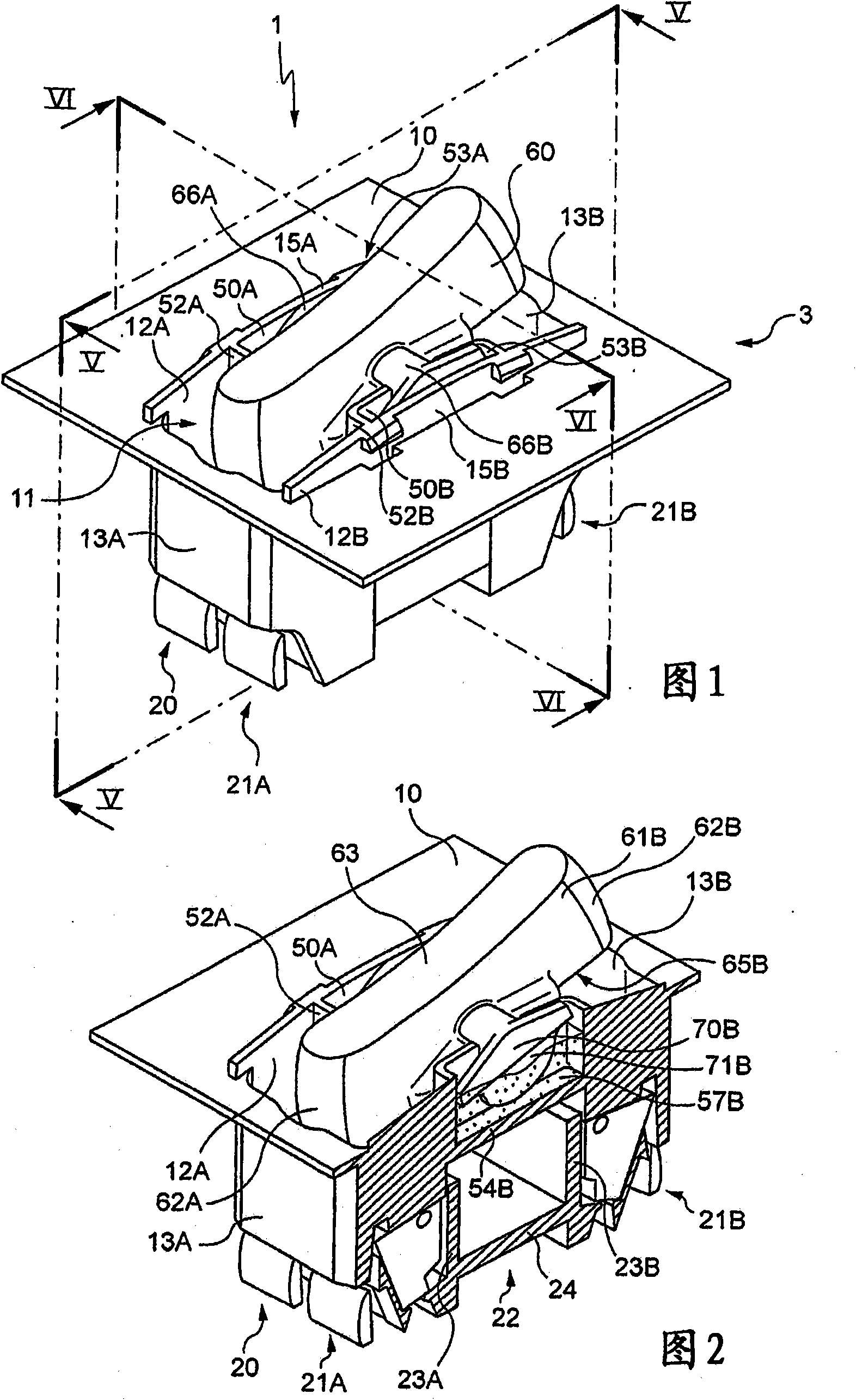
[0044] exist Figure 1 to Figure 7 The electrical equipment 1 shown in is a double switch, which includes: a key 60 pivotally mounted on the housing 3, a first fixed contact 4A ( Figure 5 ), the second fixed contact 4B which is also arranged on the housing 3 and opposite to the first fixed contact 4A, and the movable contact 5 which is rigidly connected with the key 60 .

[0045] The movable contact 5 can be alternately in two stable positions:

[0046] - a first position in which the movable contact abuts against the first fixed contact 4A and is at a distance from the second fixed contact 4B; and

[0047] -exist Figure 5 The second position shown in , in which the movable contact abuts against the second fixed contact 4B and is located at a certain distance from the first fixed contact 4A.

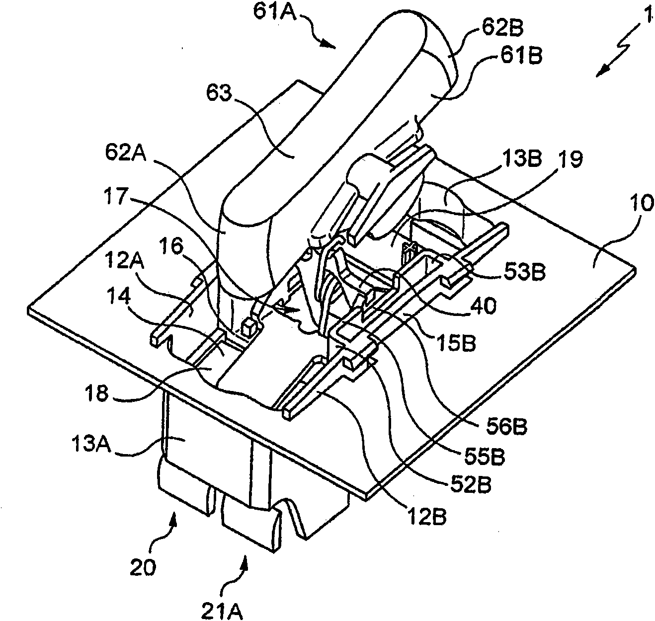
[0048] The housing 3 comprises a generally planar rectangular front wall 10 having a recess 11 in the center.

[0049] This recess 11 is delimited by two opposing longitudinal wall...


PUM


Abstract

Electrical apparatus comprises a first connection terminal (21A, 21B), a fixed contact (4A, 4B) connected electrically to said first connection terminal (21A, 21B), a second connection terminal, a movable contact (5), a conductive wiper (40) which carries said movable contact (5) and is connected electrically to said second connection terminal, a spring component for urging said wiper (40) towards either of two stable positions, specifically a conducting position in which said movable contact (5) is on the said fixed contact (4A, 4B) and an isolating position in which said movable contact (5) is not on the said fixed contact (4A, 4B), and a control member (60) connected mechanically to said conducting wiper (40); a fluid viscous substance (57B) being sandwiched between said fixed wall (12B) and said movable wall (69B) in each of said conducting and isolating positions as well as in each intermediate position between the latter.

Description

technical field [0001] The present invention generally relates to electrical equipment of the type comprising: a first terminal; a fixed contact electrically connected to said first terminal; a second terminal; a movable contact; a conductive brush (balai conducteur) connected to said second terminal, a resilient element for urging said conductive brush to move to one or the other of two stable positions, each being a a conductive position in which the movable contact abuts against the fixed contact, and a disconnected position in which the movable contact is at a distance from the fixed contact; and mechanically coupled to the conductive The manipulation part of the brush. Background technique [0002] Such electrical devices are already known, inter alia, from French patents FR 2,564,234 and FR 2,606,208. [0003] When in operation, these electrical devices are almost inevitably a source of noise detrimental to the comfort of the environment. [0004] In short, the nois...

Claims


Application Information

Patent Timeline
Patent Type & Authority Applications(China)
IPC IPC(8): H01H23/12
CPCH01H3/60H01H23/12
Inventor T·贝莱M·达科尔J-N·纪尧姆F·阿斯霍尔德E·马内罗
Owner LEGRAND SNC
Why Eureka
Try Eureka