LED (Light Emitting Diode) fluorescent lamp

An LED fluorescent lamp and lampshade technology, which is applied in the field of fluorescent lamps, can solve the problems such as the insignificant effect of the lighting angle and the insufficient lighting angle of the LED fluorescent lamp, and achieve the effect of increasing the lighting angle of the light.

Inactive Publication Date: 2011-02-16
HONG FU JIN PRECISION IND (SHENZHEN) CO LTD +1
View PDF3 Cites 9 Cited by
  • Summary
  • Abstract
  • Description
  • Claims
  • Application Information

AI Technical Summary

Problems solved by technology

In order to improve the irradiance of LED fluorescent lamps, multiple rows of light-emitting diodes (LEDs) are installed on the LED light source substrate, but all the light-emitting diodes are illuminated in the same direction, which makes the lighting angle of LED fluorescent lamps insufficient.
Also, in order to increase the il...

Method used


Image

  • LED (Light Emitting Diode) fluorescent lamp
  • LED (Light Emitting Diode) fluorescent lamp
  • LED (Light Emitting Diode) fluorescent lamp

Examples


Embodiment Construction

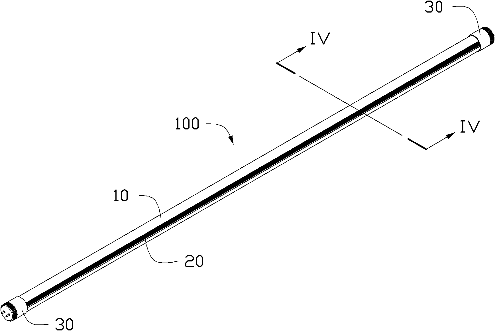
[0018] Please refer to figure 1 , In the first embodiment of the present invention, the LED fluorescent lamp 100 includes a heat dissipation base 10 , a lampshade 20 and a power connector 30 . The lampshade 20 is fixed on the heat dissipation base 10 to form a substantially elongated circular tubular structure. The power connectors 30 are arranged at two ends of the circular tube structure formed by the heat dissipation base 10 and the lampshade 20 , and the power connectors 30 are used to establish electrical connection with an external power source (not shown).

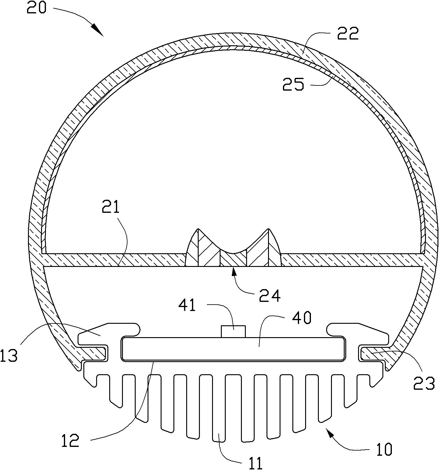
[0019] Please refer to figure 2 ,yes figure 1 The cross-sectional view of the LED fluorescent lamp along the IV-IV direction in . The LED fluorescent lamp 100 also includes a light source substrate 40 fixed on the heat dissipation base 10 , and the light source substrate 40 is electrically connected to the power connector 30 . The light source substrate 40 is provided with a light emitting diode 41 , and the li...


PUM


Abstract

The invention relates to an LED (Light Emitting Diode) fluorescent lamp comprising a base, a lamp shade and a light-source base plate, wherein the lamp shade and the light-source base plate are fixed on the base, a plurality of light emitting diodes are arranged on the light-source base plate, and a light distribution lens corresponding to the plurality of light emitting diodes is arranged between the lamp shade and the light-source base plate; the light distribution lens comprises a concave lens and a reflecting lens, wherein the reflecting lens is arranged around the concave lens, the top surface of the reflecting lens is a fully reflecting surface, and the thickness of the reflecting lens is gradually increased outwards from the concave lens; positive emitting light transmitted by the light emitting diodes passes through the concave lens and is emitted after being scattered by the concave lens; non-positive emitting light transmitted by the light emitting diodes passes through the reflecting lens and is emitted after being reflected to the outer side of the reflecting lens; and light is formed by scattering the positive emitting light through the concave lens and reflecting thenon-positive emitting light through the reflecting lens, has a larger optical illumination angle and strong lateral illumination light and is even and soft.

Description

technical field [0001] The invention relates to a fluorescent lamp, in particular to an LED fluorescent lamp. Background technique [0002] Compared with traditional light sources, light-emitting diodes (LEDs) have the advantages of higher luminous efficiency, low radiation, low power consumption, long life, low driving voltage, fast startup, environmental protection, shock resistance and pressure resistance, and miniaturization of lamps. Illuminating devices as a fluorescent light source are currently widely used to replace gas fluorescent fluorescent lamps. [0003] Existing LED fluorescent lamps usually consist of a cylindrical transparent lamp tube and an LED light source substrate installed in the lamp tube. In order to improve the irradiance of the LED fluorescent lamp, multiple rows of light-emitting diodes (LEDs) are installed on the LED light source substrate, but all the LEDs illuminate in the same direction, which makes the lighting angle of the LED fluorescent l...

Claims


Application Information

Patent Timeline
IPC IPC(8): F21V5/08F21S2/00F21V3/04F21V29/00F21V17/10F21V5/04F21Y101/02
CPCF21V5/00F21K9/17F21V17/104F21V7/0091F21Y2103/003F21Y2101/02F21K9/27F21Y2103/10F21Y2115/10F21K9/69F21K9/68
Inventor 章绍汉
Owner HONG FU JIN PRECISION IND (SHENZHEN) CO LTD
Why Eureka
Try Eureka