Heating system using self-operated three-way water-mixing temperature regulating valve

A technology of mixing water temperature and heating system, which is applied in heating system, multi-way valve, household heating, etc., to achieve the effect of simple equipment and avoiding imbalance

Inactive Publication Date: 2011-02-16
HARBIN INST OF TECH
View PDF6 Cites 3 Cited by
  • Summary
  • Abstract
  • Description
  • Claims
  • Application Information

AI Technical Summary

Problems solved by technology

There is a lack of a self-operated three-way regulating valve that can adjust the mixed water flow according to a certain inlet temperature

Method used


Image

  • Heating system using self-operated three-way water-mixing temperature regulating valve
  • Heating system using self-operated three-way water-mixing temperature regulating valve
  • Heating system using self-operated three-way water-mixing temperature regulating valve

Examples


specific Embodiment approach 1

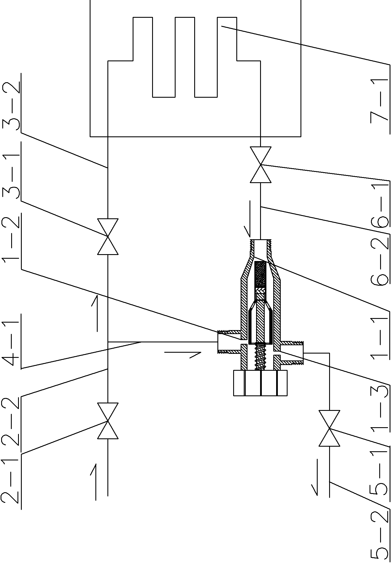
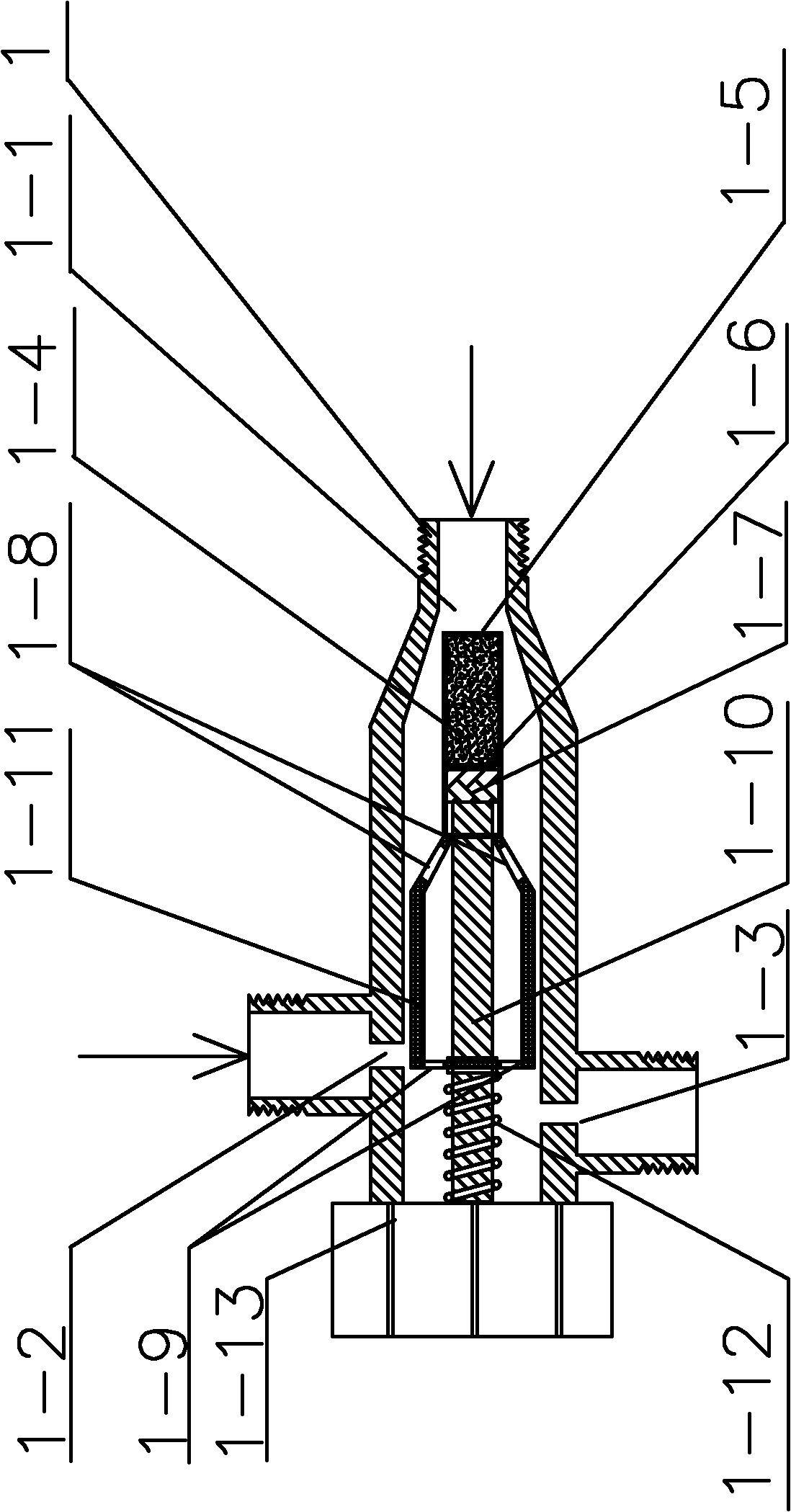
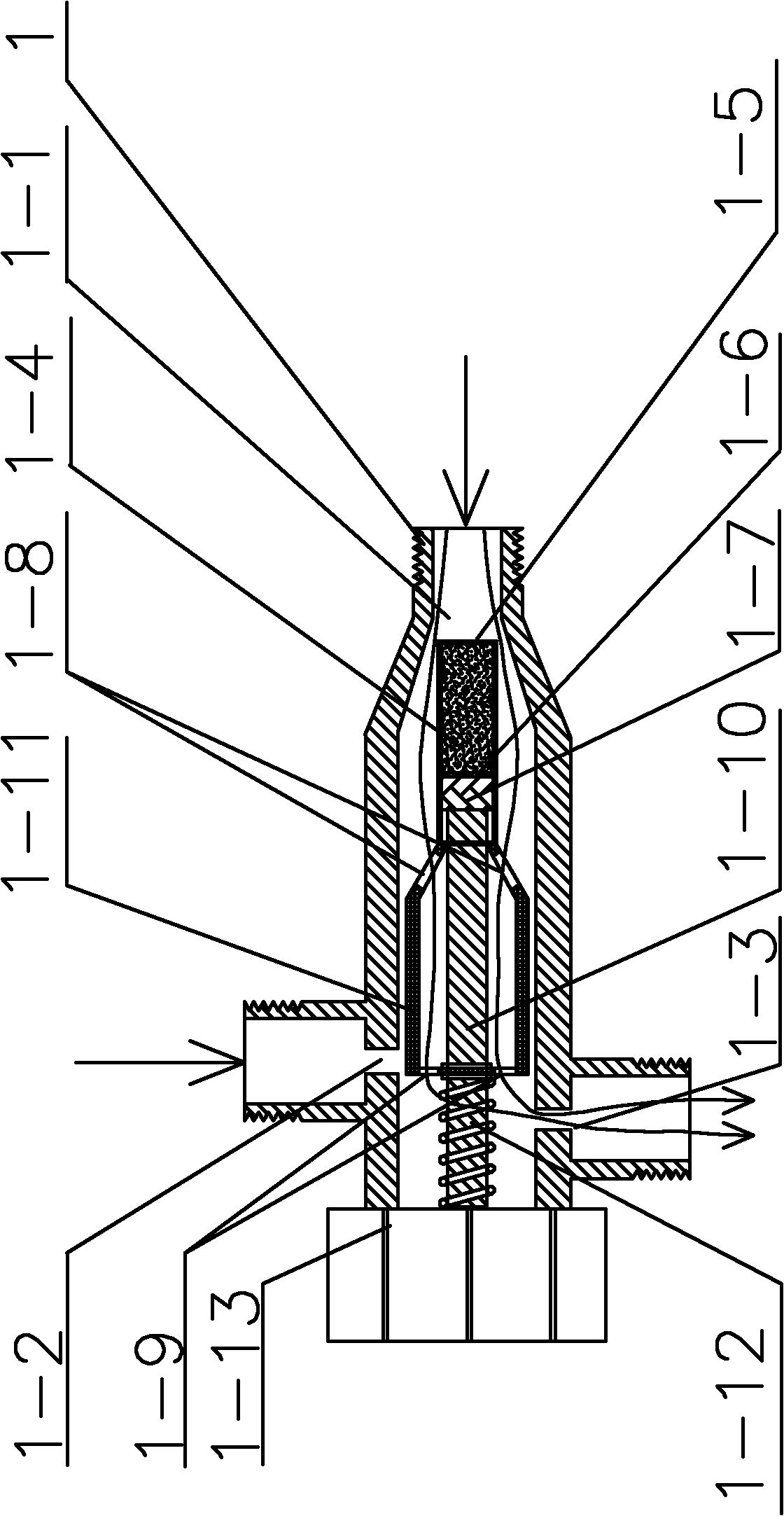
[0009] Specific implementation mode one: combine figure 1 and figure 2 Describe this embodiment, the system of this embodiment includes external network water supply pipe 2-2, user water supply pipe 3-2, bypass water mixing pipe 4-1, external network return water pipe 5-2, user return water pipe 6-2 and multiple A series heating user 7-1, characterized in that the system also includes a temperature regulating valve, the temperature regulating valve is composed of a valve body 1, a paraffin temperature package 1-4, a metal shell 1-5, a diaphragm 1-6, a rubber Plug 1-7, valve core 1-8 with water inlet, valve core 1-9 with water outlet, nylon connecting rod 1-10, nylon valve core 1-11, spring 1-12 and temperature control handle 1-13 One end of the valve body 1 is a small-diameter end, the other end of the valve body 1 is a large-diameter end, the small-diameter end of the valve body 1 is the first inlet 1-1, and the side wall of the upper end of the valve body 1 is provided wit...

specific Embodiment approach 2

[0011] Specific implementation mode two: combination figure 1 To illustrate this embodiment, the system of this embodiment also includes an external network water supply regulating valve 2-1, and the external network water supply pipe 2-2 is provided with an external network water supply regulating valve 2-1, and this structure is used to adjust the external network water supply. Other components and connections are the same as those in the first embodiment.

specific Embodiment approach 3

[0012] Specific implementation mode three: combination figure 1 To illustrate this embodiment, the system of this embodiment also includes a user water supply regulating valve 3-1, and the user water supply pipe 3-2 is provided with a user water supply regulating valve 3-1, and this structure is used to regulate the user water supply. Other components and connections are the same as those in the first embodiment.


PUM


Abstract

The invention discloses a heating system using a self-operated three-way water-mixing temperature regulating valve, which relates to a heating system. The invention aims to solve the problem of lack of a self-operated three-way regulating valve in the heating system capable of regulating the water mixing flow rate according to the temperature of a certain inlet. The minor diameter end of the valve body is a first inlet; the upper end side wall of the valve body is provided with a second water inlet, and the lower end side wall of the valve body is provided with a first water outlet; a paraffin thermometer bulb, a metal casing, a diaphragm, a rubber stopper, a valve core with a water inlet, a valve core with a water outlet, a nylon connecting rod, a nylon valve core and a spring are arranged in the valve body; an external water supply pipe is respectively communicated with a bypass water mixing pipe and a user water supply pipe; the bypass water mixing pipe is communicated with the second water inlet of the valve body; the user water supply pipe is communicated with the first user in a plurality of series heating users; the last user in the series heating users is communicated with a user return water pipe; the user return water pipe is communicated with the first water inlet of the valve body; and the first water outlet of the valve body is communicated with an external return water pipe. The invention is used for resident heating.

Description

technical field [0001] The invention relates to a heating system. Background technique [0002] my country's heating energy consumption is huge, and with the continuous improvement of people's living standards, the heating area will become larger and larger. It is of great significance to carry out heating and energy saving. In order to achieve both comfortable and economical heating, it is necessary to adjust the flow, temperature and pressure of the heat medium in the heating system. The automatic control of central heating and heating system is an important measure to ensure the normal operation of the heating system and meet the requirements of energy saving, and it is also one of the symbols of the modernization of heating technology. In the past, my country's heating system monitoring and adjustment equipment was backward, and the energy consumption was relatively high. In order to ensure the safe, reliable and energy-saving operation of the heating system; the comf...

Claims


Application Information

Patent Timeline
Patent Type & Authority Applications(China)
IPC IPC(8): F16K11/02F24D19/10
Inventor 姜永成方修睦梁元元
Owner HARBIN INST OF TECH
Why Eureka
Try Eureka