Blood pressure information measurement device

A measuring device and blood pressure technology, which can be used in vascular assessment, cardiac catheterization, etc., can solve the problems of complicated dilation operations, and achieve stable measurement and good use convenience

Active Publication Date: 2011-02-16
OMRON HEALTHCARE CO LTD
View PDF4 Cites 10 Cited by
  • Summary
  • Abstract
  • Description
  • Claims
  • Application Information

AI Technical Summary

Problems solved by technology

That is, when putting on the cuff, it is necessary to temporarily expand the collar in a reduced diameter state and put it on the site to be measured, and this expansion operation becomes complicated.

Method used


Image

  • Blood pressure information measurement device
  • Blood pressure information measurement device
  • Blood pressure information measurement device

Examples


no. 1 approach

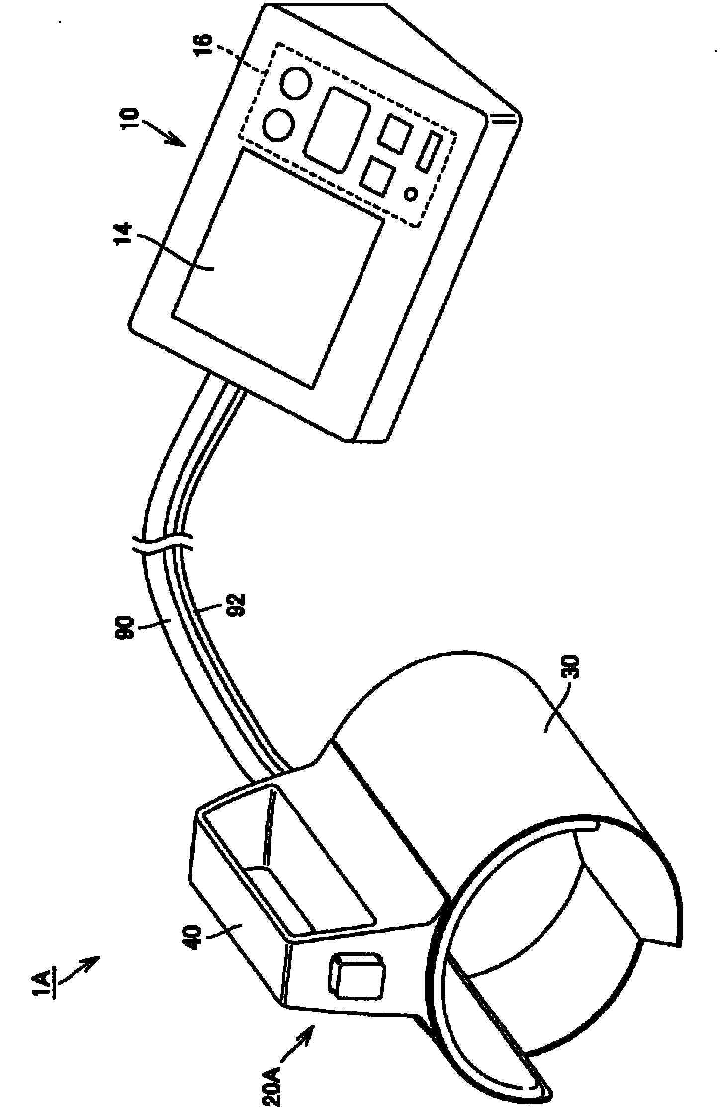
[0095] figure 1 It is a figure which shows the appearance structure of the sphygmomanometer which concerns on 1st Embodiment of this invention. First, refer to figure 1 The external configuration of the sphygmomanometer 1A of this embodiment will be described.

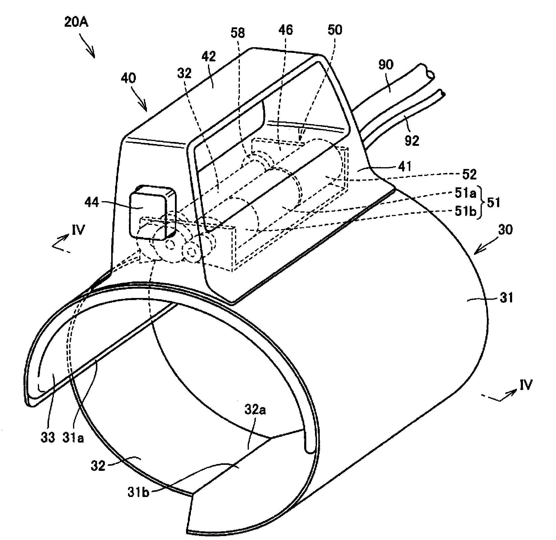
[0096] Such as figure 1 As shown, the sphygmomanometer 1A of this embodiment has a main body 10 , a cuff 20A, an air tube 90 , and a connection cable 92 . The main body 10 has a box-shaped frame body, and a display unit 14 and an operation unit 16 are provided on the upper surface thereof. The main body 10 is used by being mounted on a mounting surface such as a table during measurement. The cuff 20A has a cylindrical cuff main body 30 having a hollow opening through which an upper arm can be inserted in the axial direction, and a handle 40 provided on an outer peripheral surface of the cuff main body 30 . The cuff 20A is worn on the upper arm and used during measurement. The air tube 90 and the connection cable ...

no. 2 approach

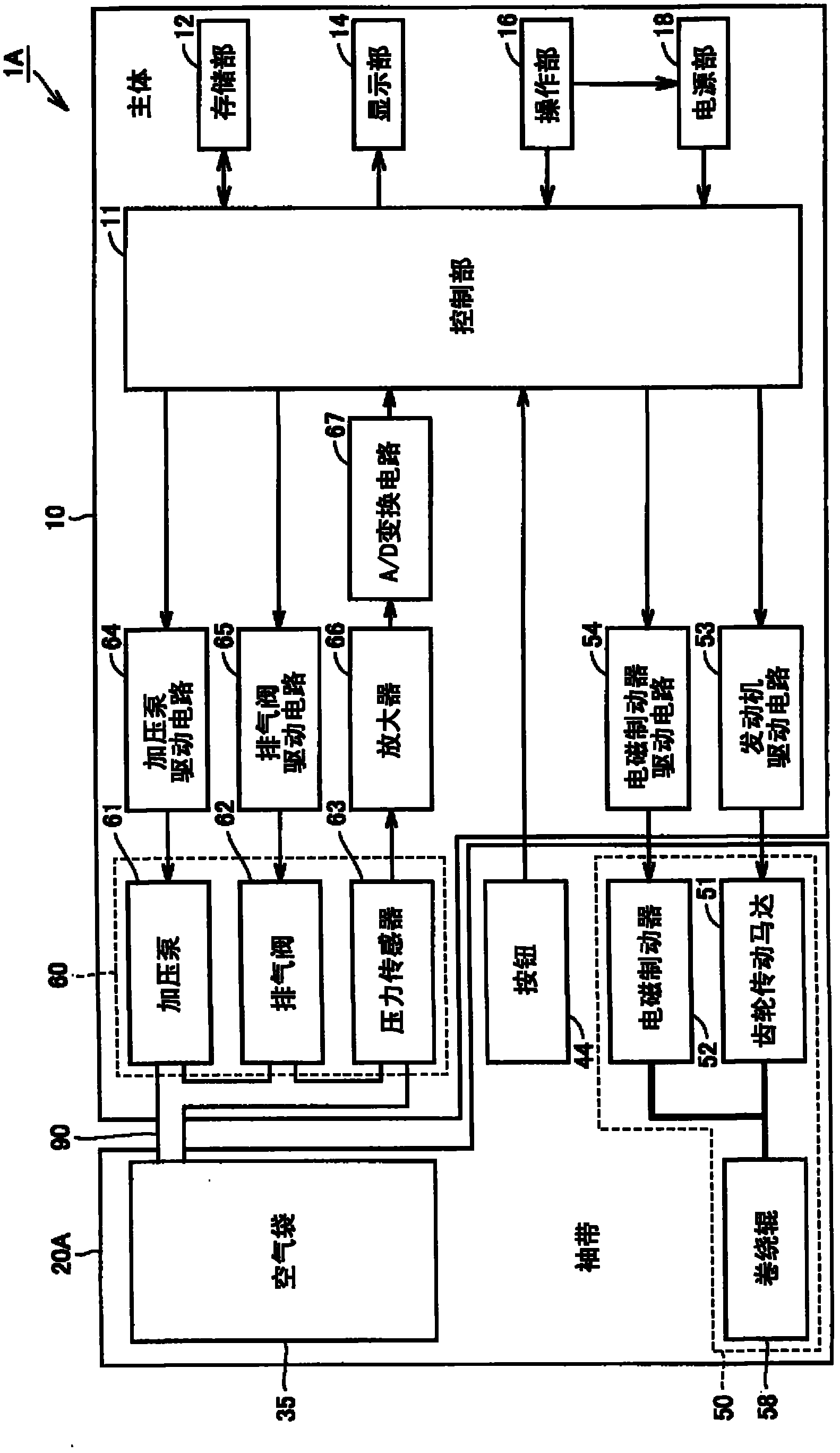
[0142] Figure 10 It is a diagram showing the configuration of functional blocks of the sphygmomanometer according to the second embodiment of the present invention. First, refer to Figure 10 , and the structure of the functional blocks of the blood pressure monitor 1B of this embodiment will be described. In addition, the sphygmomanometer 1B of the present embodiment has the same appearance structure as the sphygmomanometer 1A of the first embodiment described above, and most of the functional block structures are common. Therefore, the same reference numerals are assigned to the same parts as in the above-mentioned first embodiment in the drawings, and description thereof will not be repeated here.

[0143] The sphygmomanometer 1A of the above-mentioned first embodiment utilizes the air bag 35 and the air system unit 60 as the clamping force detection mechanism for detecting the clamping force of the clamping belts 31 and 32 on the upper arm 202, and captures the clamping...


PUM


Abstract

A sphygmomanometer is separated into a cuff (20A) including an air bag, and a body provided with an expansion / contraction mechanism for expanding / contracting the air bag, wherein the cuff (20A) includes a tubular cuff body portion (30) into which an upper arm can be inserted, and a grip portion (40) provided on the outer circumferential surface of the cuff body portion (30). The cuff body portion(30) has fastening belts (31, 32) wound around the outside of the air bag, and a fastening length adjustment mechanism (50) which adjusts the fastening length of the fastening belts (31, 32) for the upper arm. The fastening length adjustment mechanism (50) includes a winding roller (58) which can wind and feed the fastening belts (31, 32), a geared motor (51) for rotary driving the winding roller(58), and an electromagnetic brake (52) for applying a braking force to the winding roller (58). With such an arrangement, a cuff can be attached easily to a part being measured in a sphygmomanometerwhere a cuff and a body are separated, and reliable winding of a cuff for a part being measured is reproduced every time when blood pressure is measured.

Description

technical field [0001] The present invention relates to a blood pressure information measuring device capable of measuring blood pressure information such as a blood pressure value, and more particularly to a blood pressure information measuring device configured separately into a cuff worn on a site to be measured and a main body mounted on a mounting surface for use. Background technique [0002] Obtaining the blood pressure information of the subject is very important in knowing the health status of the subject. In recent years, attempts have been made not only to obtain systolic blood pressure values ​​(highest blood pressure values) and diastolic blood pressure values ​​(lowest blood pressure values) whose usefulness has been widely recognized as representative indicators of health management, but also to capture cardiac load or arterial blood pressure. Changes in hardness and the like are also attempted to capture changes in cardiac load and arterial hardness by acquir...

Claims


Application Information

Patent Timeline
Patent Type & Authority Applications(China)
IPC IPC(8): A61B5/022
CPCA61B5/02141A61B5/02233
Inventor 佐野佳彦上坂知里有贺裕恭
Owner OMRON HEALTHCARE CO LTD
Why Eureka
Try Eureka