Optical member, lighting device, display device, television receiver and manufacturing method of optical member

A technology of optical components and manufacturing methods, applied in optical elements, optics, nonlinear optics, etc., can solve the problems of outgoing light diffusion and low light utilization efficiency, and achieve the effect of suppressing moiré

Inactive Publication Date: 2011-02-16
SHARP KK
View PDF5 Cites 17 Cited by
  • Summary
  • Abstract
  • Description
  • Claims
  • Application Information

AI Technical Summary

Problems solved by technology

In the optical member of such a laminated structure, there is a problem that the outgoing light tends to diffuse in a direction not used for display, and the utilization efficiency of light is low.

Method used


Image

  • Optical member, lighting device, display device, television receiver and manufacturing method of optical member
  • Optical member, lighting device, display device, television receiver and manufacturing method of optical member
  • Optical member, lighting device, display device, television receiver and manufacturing method of optical member

Examples


Embodiment approach 1

[0063] pass Figure 1 to Figure 20 Embodiment 1 of the present invention will be described.

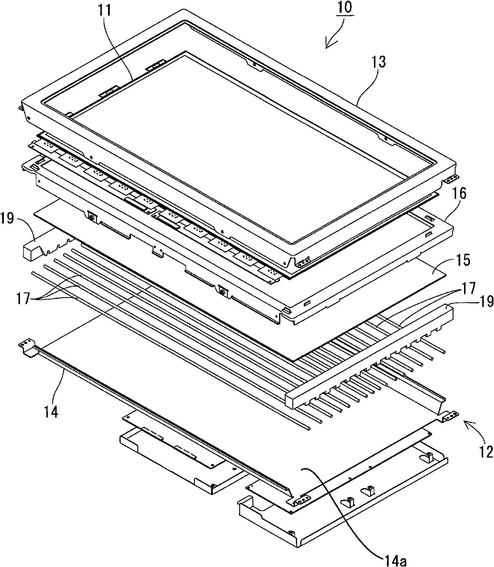
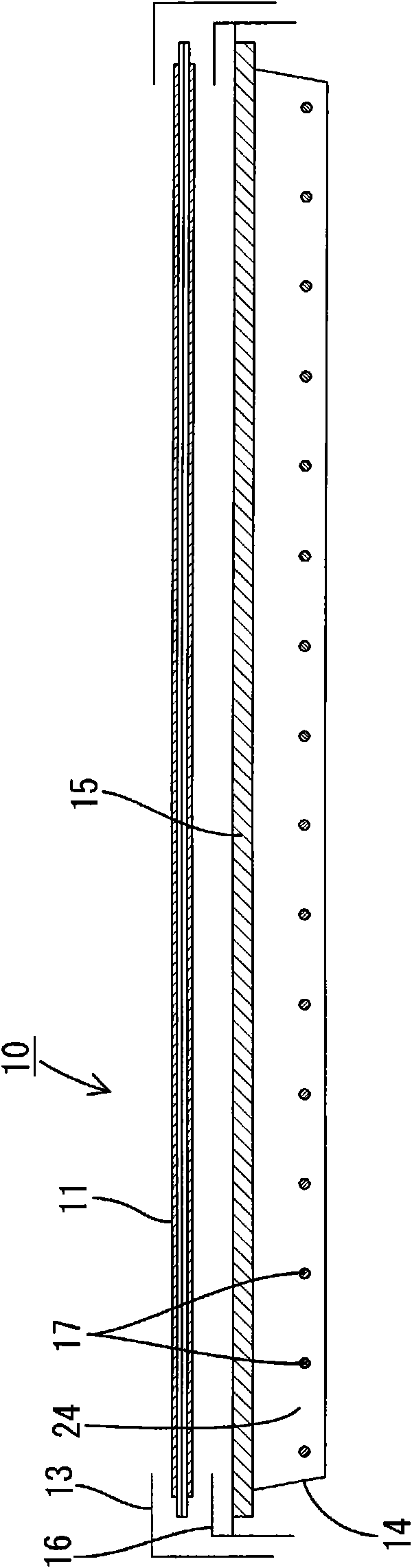
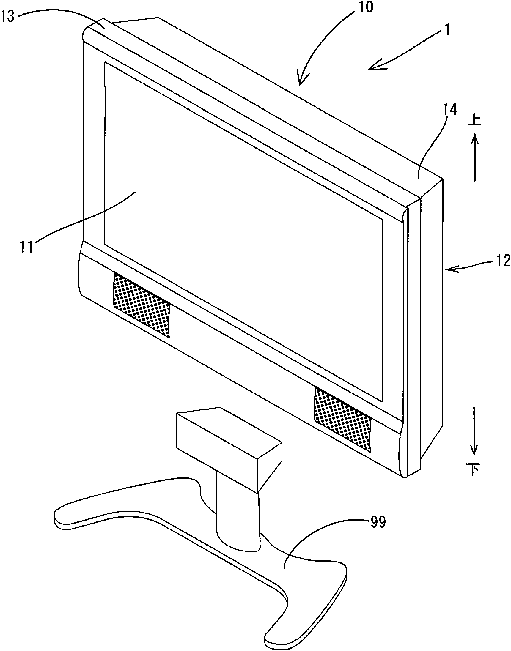
[0064] The liquid crystal display device 10 of this embodiment is as figure 1 with figure 2 As shown, a rectangular liquid crystal panel (display panel) 11 in plan view and a backlight device (illumination device) 12 as an external light source are provided, and they are integrally held by a case 13 or the like. The liquid crystal display device 10 is, for example, image 3 As shown, it can be applied to a television receiving device 1, which is composed of a liquid crystal display device 10 and a base 99 supporting the liquid crystal display device 10 from below. The liquid crystal panel 11 and the backlight device 12.

[0065] The liquid crystal panel 11 has a well-known structure in which a liquid crystal (liquid crystal layer) whose optical properties change according to an applied voltage is sealed in a gap between a transparent TFT substrate and a transparent CF substrate....

Embodiment approach 2

[0118] pass Figure 21 or Figure 22 Embodiment 2 of the present invention will be described. In Embodiment 2, it is shown that the microlenses 23 employ two types of sizes, large and small. In addition, in this second embodiment, redundant descriptions of the same structures, operations, and effects as those of the above-mentioned first embodiment will be omitted.

[0119] The microlenses 23 formed in the optical member 15 of the present embodiment have two types of planar view sizes, including large microlenses 23A and small microlenses 23B. In the present embodiment, moiré is suppressed by setting the difference between the planar size of the large microlens 23A and the small microlens 23B and the planar size of the pixel PE of the liquid crystal panel 11 to be equal or greater.

[0120] The specific setting of the plan view size of the large and small microlenses 23 will be described in detail. When the plan view size of the large microlens 23A is Lm1 and the plan view...


PUM


Abstract

An optical member 15 is provided with a planar light transmitting sheet (22), and many convex random microlenses 23 arranged within a surface of the light transmitting sheet 22. Since the many convex random microlenses 23 are arranged within the surface of the light transmitting sheet 22, generation of moire is suppressed even when the optical member is overlapped with a liquid crystal panel 11 having cyclically arranged pixels PE.

Description

technical field [0001] The present invention relates to an optical member, a lighting device, a display device, a television receiver, and a method of manufacturing the optical member. Background technique [0002] A liquid crystal display device generally includes a liquid crystal panel as a display panel and a backlight as an external light source provided on the rear side of the liquid crystal panel. Among them, in the backlight, cold cathode tubes are provided as a plurality of linear light sources, and optical members are provided on the light emitting side of the cold cathode tubes, and the optical members are used to convert the light emitted from each cold cathode tube into Uniform surface. There are optical members having a structure in which, for example, a plurality of diffusion plates, diffusion sheets, lens sheets, brightness improvement sheets, and the like are laminated. In an optical member with such a laminated structure, there is a problem that emitted li...

Claims


Application Information

Patent Timeline
Patent Type & Authority Applications(China)
IPC IPC(8): G02F1/13357G02B5/02G02F1/1335G02B3/00
CPCG02F1/133606G02B3/0043G02F2001/133607G02F1/133607
Inventor 鹰田良树
Owner SHARP KK
Why Eureka
Try Eureka