Device for arranging and debugging linear laser light source and method thereof

A linear laser, installation and debugging technology, applied in the direction of electrical digital data processing, input/output process of data processing, instruments, etc., can solve the problem of affecting the positioning accuracy, inaccurate installation of linear laser light sources, and difficulty in judging a word Whether the optical axis of the linear laser light source is parallel to the touch panel, etc., to achieve an accurate and convenient debugging process

Inactive Publication Date: 2011-02-23
GUANGDONG VTRON TECH CO LTD
View PDF3 Cites 8 Cited by
  • Summary
  • Abstract
  • Description
  • Claims
  • Application Information

AI Technical Summary

Problems solved by technology

[0003] During the installation and debugging process, since the human eyes cannot directly see the infrared linear laser light source, and directly rely on manual adjustments blindly, it is difficult to judge whether the optical axis of the linear laser light

Method used


Image

  • Device for arranging and debugging linear laser light source and method thereof
  • Device for arranging and debugging linear laser light source and method thereof
  • Device for arranging and debugging linear laser light source and method thereof

Examples


Embodiment 1

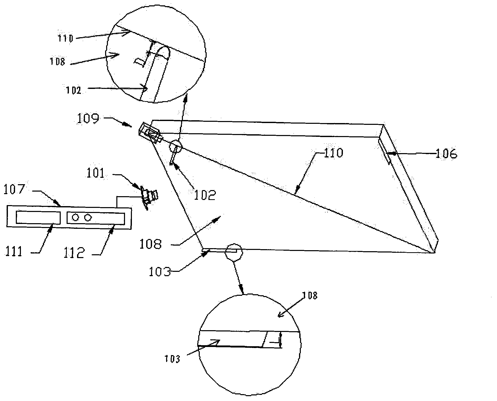
[0042] see figure 1 As shown, the linear laser light source is placed on the corner of the touch panel. In the case of needing multiple inline laser light sources, since each inline laser light source is in this situation, the device and method for installation and debugging are similar, this embodiment only illustrates the specific implementation steps of one inline laser light source .

[0043] The device for installing and debugging an inline laser light source of the present invention is composed of a camera 101 , a passive pen 102 , reflective strips 103 and 106 , and a debugging instruction module 107 .

[0044] Wherein, the reflective strips 103, 106 are respectively placed on the two intersection positions of the two illumination boundary lines of the inline laser light source required by the touch panel and the frame of the touch panel; in this embodiment, the reflective strips It is white paper with a height L of 5mm.

[0045]The camera 101 is placed at a positio...

Embodiment 2

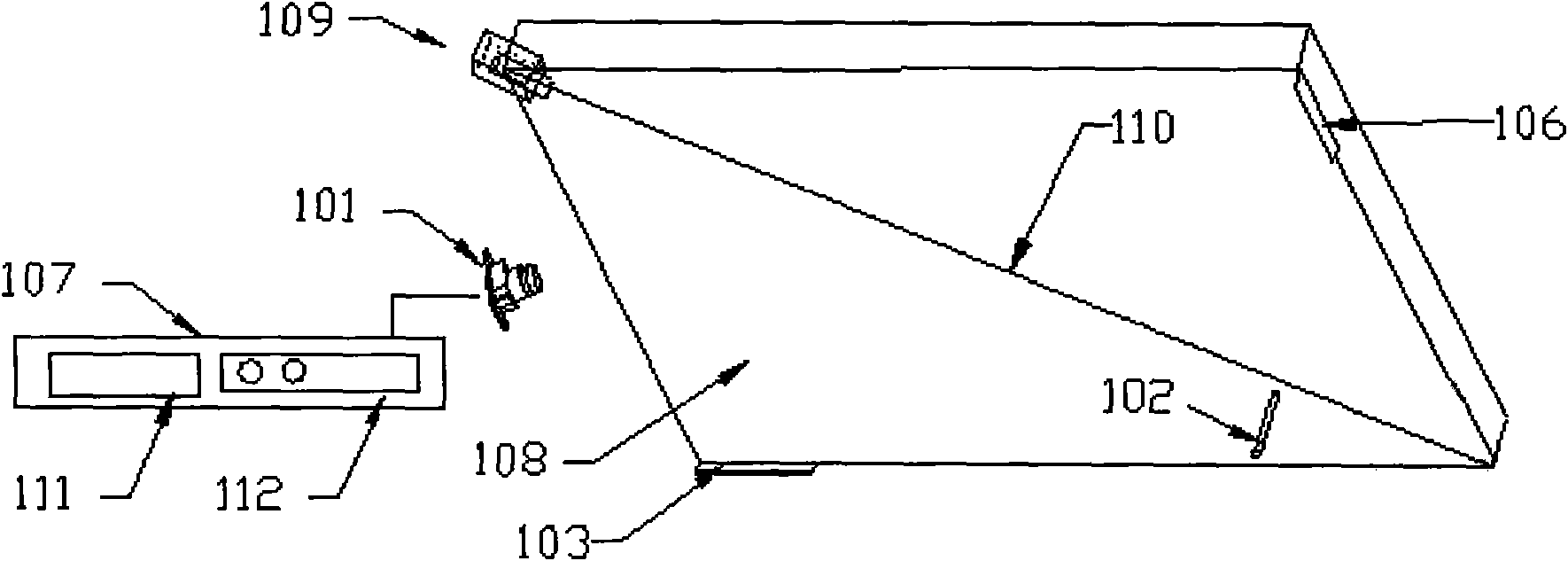
[0066] see Image 6 As shown, the difference between this embodiment and the previous embodiment is that the linear laser light source is placed on the edge of the touch panel, while the previous embodiment is placed on the corner of the touch panel. Since the installation and debugging devices and methods of each inline laser light source are similar in this situation, this embodiment only illustrates the specific implementation steps of one inline laser light source.

[0067] A device for installing and debugging an inline laser light source of the present invention is composed of a camera 101 , a passive pen 102 , reflective strips 103 and 104 , and a debugging indicator module 107 .

[0068] Wherein, the reflective strips 103, 104 are placed on the two intersection positions of the two illumination boundary lines of the linear laser light source required by the touch panel and the two intersection positions of the touch panel frame; the reflective strips are white paper or...


PUM

PropertyMeasurementUnit
Heightaaaaaaaaaa

Abstract

The invention discloses a device for arranging and debugging a linear laser light source, which consists of a camera, a passive pen, reflective stripes and a debugging indication module, wherein the reflective stripes are used for reflecting light rays emitted from the linear laser light source; the camera shoots an image and outputs the shot image; the debugging indication module consists of a debugging unit and a signal display unit; and when the image is shot, a pen point of the passive pen is downwards vertically arranged at two positions at different distances away from the linear laser light source on a central optical axis of the linear laser light source on a touch panel respectively. The invention also discloses a method for arranging and debugging the linear laser light source. According to the position, illuminated by the laser light source, of the passive pen in the image shot by the camera and the brightness of the reflective stripes, the optical axis of the linear laser light source is adjusted to be parallel to the touch panel, and the illumination range of the linear laser light source is ensured to cover the whole touch panel so as to finish the debugging of the linear laser light source accurately and conveniently.

Description

technical field [0001] The invention relates to the field of laser light source positioning, in particular to a device and method for installing and debugging an inline laser light source. Background technique [0002] With the wide application of touch positioning technology, there are more and more positioning forms, including resistive, capacitive, infrared, surface acoustic wave, etc., and a recent laser-based positioning technology, which has high positioning accuracy. , can realize the characteristics of multi-point positioning and fast response speed, the Chinese invention patent application with the patent publication number CN101477427A discloses "contact or non-touch infrared laser multi-touch device", through at least one detection direction of the touch panel Or multiple infrared lasers are installed on multiple corners. When a touch event occurs, the infrared camera captures the infrared light scattered by the touch point for positioning. When installing the de...

Claims


Application Information

Patent Timeline
IPC IPC(8): G06F3/042
Inventor 彭昌辉刘志文钟杰婷刘小青
Owner GUANGDONG VTRON TECH CO LTD
Why Eureka
Try Eureka