Novel filter capable of measuring liquid flow rate and continuously working

A liquid flow and filter technology, which is used in fixed filter element filters, electromagnetic flowmeters to detect fluid flow, volume/mass flow generated by electromagnetic effects, etc. question

Inactive Publication Date: 2011-03-30
DONGHUA UNIV
View PDF5 Cites 18 Cited by
  • Summary
  • Abstract
  • Description
  • Claims
  • Application Information

AI Technical Summary

Problems solved by technology

At present, there are many types of filters on the market, but after working for a period of time, as the amount of impurities increases, these filters have to stop running to remove them for cleaning, or remove a certain part for cleaning, which affects the system. continuously working
Moreover, the existing filters usually install a pressure gauge before and after the filter to detect the stability and resistance of the fluid before and after the filter, which leads to the structure of the filter being not simple enough.

Method used


Image

  • Novel filter capable of measuring liquid flow rate and continuously working
  • Novel filter capable of measuring liquid flow rate and continuously working
  • Novel filter capable of measuring liquid flow rate and continuously working

Examples


Embodiment 1

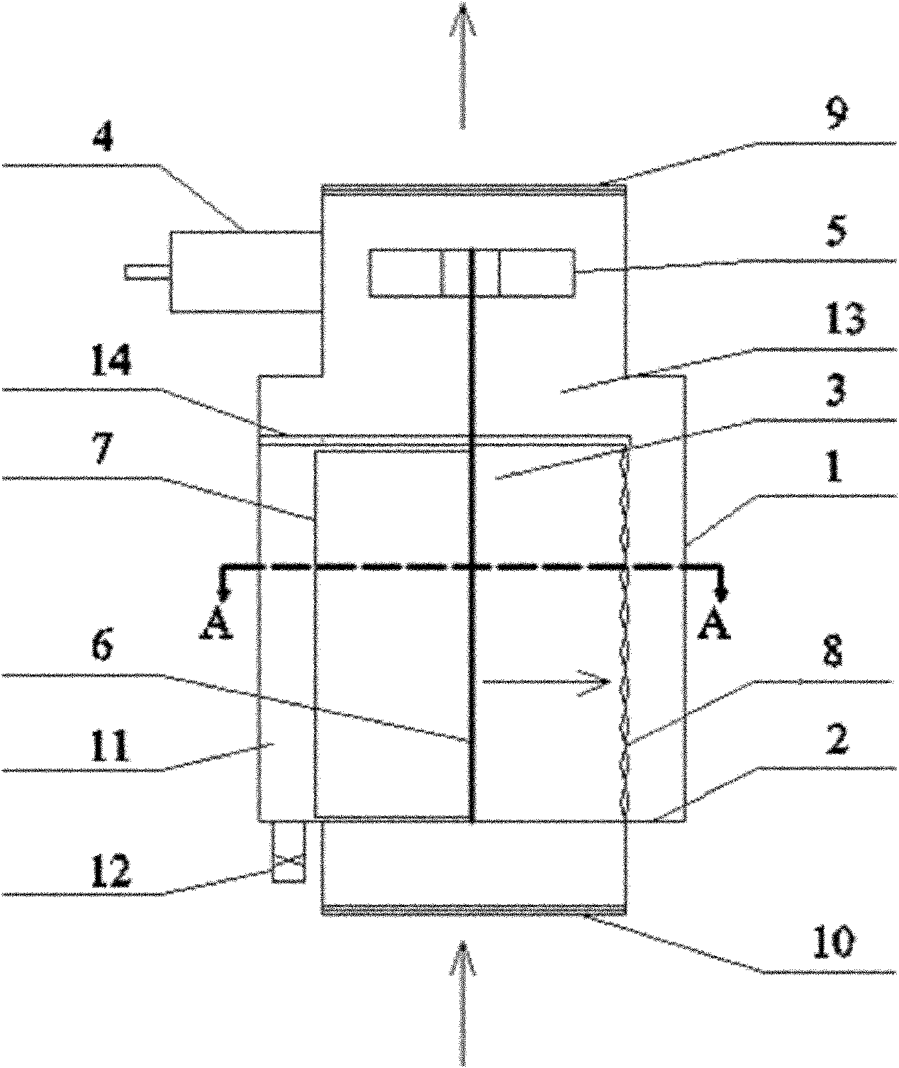
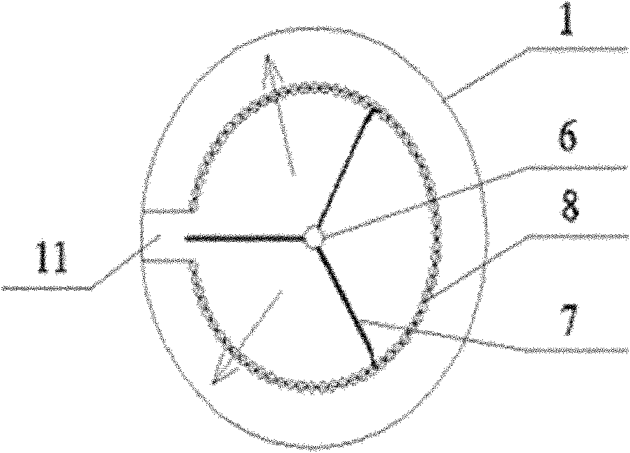
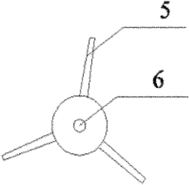
[0021] This embodiment includes a filter body 1 , a bottom plate 2 , an inner core 3 , and an electromagnetic induction signal device 4 . Inner core 3 is made up of impeller 5, rotating shaft 6, scraper 7, filter screen 8, is connected as a whole with rotating shaft as the center, goes deep into from the bottom of meter body during installation, directly be stuck on the positioning groove 14 on the side of meter body. The body 1 and the inner core 3 form two spaces to separate the fluid from the impurities. The fluid flows out from around the filter screen 8 into the fluid area 13 , and the impurities enter into the impurity area 11 .

[0022] There is a fluid inlet 10 and a control valve 12 on the bottom plate 2, and the fluid outlet 9 is on the top of the meter body. The fluid inlet 10 and the fluid outlet 9 are connected with the water pipes at both ends of the meter body by threaded buckles. After the fluid flows from the fluid inlet 10 through the filter screen 8, impuri...

Embodiment 2

[0025] This embodiment includes a filter body 1 , a bottom plate 2 , an inner core 3 , and an electromagnetic induction signal device 4 . Inner core 3 is made up of impeller 5, rotating shaft 6, scraper 7, filter screen 8, is connected as a whole with rotating shaft as the center, goes deep into from the bottom of meter body during installation, directly be stuck on the positioning groove 14 on the side of meter body. The body 1 and the inner core 3 form two spaces to separate the fluid from the impurities. The fluid flows out from around the filter screen 8 into the fluid area 13 , and the impurities enter into the impurity area 11 .

[0026] There is a fluid inlet 10 and a control valve 12 on the bottom plate 2, and the fluid outlet 9 is on the top of the meter body. The fluid inlet 10 and the fluid outlet 9 are connected with the water pipes at both ends of the meter body by threaded buckles. After the fluid flows from the fluid inlet 10 through the filter screen 8, impuri...

Embodiment 3

[0029]This embodiment includes a filter body 1 , a bottom plate 2 , an inner core 3 , and an electromagnetic induction signal device 4 . Inner core 3 is made up of impeller 5, rotating shaft 6, scraper 7, filter screen 8, is connected as a whole with rotating shaft as the center, goes deep into from the bottom of meter body during installation, directly be stuck on the positioning groove 14 on the side of meter body. The body 1 and the inner core 3 form two spaces to separate the fluid from the impurities. The fluid flows out from around the filter screen 8 into the fluid area 13 , and the impurities enter into the impurity area 11 .

[0030] There is a fluid inlet 10 and a control valve 12 on the bottom plate 2, and the fluid outlet 9 is on the top of the meter body. The fluid inlet 10 and the fluid outlet 9 are flanged to the water pipes at both ends of the meter body. After the fluid flows from the fluid inlet 10 through the filter screen 8, impurities remain on the inner ...


PUM


Abstract

The invention relates to a novel filter capable of measuring liquid flow rate and continuously working, which comprises a surface body, a bottom plate, an inner core and an electromagnetic sensing annunciator. The inner core is a main structure part and consists of an impeller, a rotating shaft, a filtering screen and a scrapper. The surface body and the inner core form two channels to separate fluid from impurities. The fluid flows into the filtering screen from the bottom plate, flows out from the surrounding part, and flows by the impeller, and finally flows out from the top end of the surface body. The impeller is driven to rotate when the fluid flows by the impeller, and the rotation speed of the impeller and the fluid quantity have fixed quantity relation, the change of the flow rate can be displayed and the stability of the system can also be detected. Meanwhile, because the impeller is coaxial to the scrapper, the scrapper is driven to rotate to automatically clean impurities on the inner wall of the filtering screen; the impurities can also be cleared when the system runs so as to ensure the continuity of filtering operation. The invention also has functions of a flowmeter and a filter; and therefore, the filter has strong practicability.

Description

technical field [0001] The invention relates to a fluid filter, in particular to a novel filter capable of measuring liquid flow and working continuously. Background technique [0002] The filter is an indispensable device on the conveying medium pipeline. It is usually installed at the inlet end of the pressure reducing valve, pressure relief valve, fixed water level valve or other equipment to eliminate impurities in the medium to protect the normal operation of the valve or equipment. use. At present, there are many types of filters on the market, but after working for a period of time, as the amount of impurities increases, these filters have to stop running to remove them for cleaning, or remove a certain part for cleaning, which affects the system. continuously working. Moreover, the existing filter usually adopts the method of installing a pressure gauge before and after the filter to detect the stability and resistance of the fluid before and after the filter, whic...

Claims


Application Information

Patent Timeline
Patent Type & Authority Applications(China)
IPC IPC(8): B01D35/02B01D29/35B01D29/64G01F1/58
Inventor 刘刚杨小平杨其才蒋雅靖甘长德
Owner DONGHUA UNIV
Why Eureka
Try Eureka