Chamfering method of optical lens for camera

A technology of optical lenses and cameras, which is applied in the direction of abrasives, metal processing equipment, manufacturing tools, etc., can solve the problem that chamfering cannot be produced in batches, and achieve the effect of improving production efficiency

Inactive Publication Date: 2011-03-30
SHENZHEN O FILM TECH
View PDF2 Cites 2 Cited by
  • Summary
  • Abstract
  • Description
  • Claims
  • Application Information

AI Technical Summary

Problems solved by technology

[0003] The object of the present invention is to provide a method for chamfering optical lenses for cameras, which can chamfer multiple lenses at the same time, solve the problem that the chamfering of smaller lenses cannot be produced in batches, and greatly improve production efficiency

Method used


Image

  • Chamfering method of optical lens for camera
  • Chamfering method of optical lens for camera
  • Chamfering method of optical lens for camera

Examples


Embodiment 1

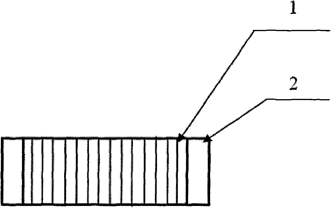
[0030] Step 1: Evenly stack multiple lenses (1) to be edged, place two pieces of ordinary glass (2) at both ends, and then place them in a container with wax, so that the wax can completely soak into the gap between the lenses , bond a plurality of lenses to form a lens column, if it is a disc, grind the lens column into a cylinder to form a cylindrical lens column, such as figure 1 .

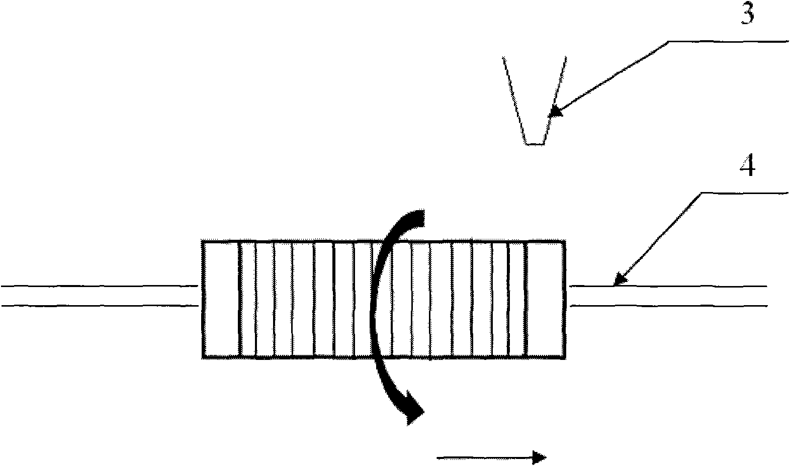
[0031] Step 2: Lift both ends of the lens column with thimbles (4), the middle is hollow, and make it rotate at a high speed around the horizontal line where the thimble (3) is located, and move horizontally evenly at the same time, as figure 2 .

[0032] Step 3: Use a high-pressure spray gun (4) to evenly spray emery onto the lens column. After spraying, the lens and the wax sticky area are sprayed into a "V" shape to form a chamfered lens (11), such as Figure 4 . The water-sand mixture is used for spraying. The water can cool the heat generated during spraying, and can take away the glas...

Embodiment 2

[0034] In Embodiment 1, the lens column is used to rotate at a high speed with the horizontal line where the thimble is located as the axis, and at the same time move horizontally evenly. This embodiment makes the following improvements to Step 2 and Step 3 in Embodiment 1:

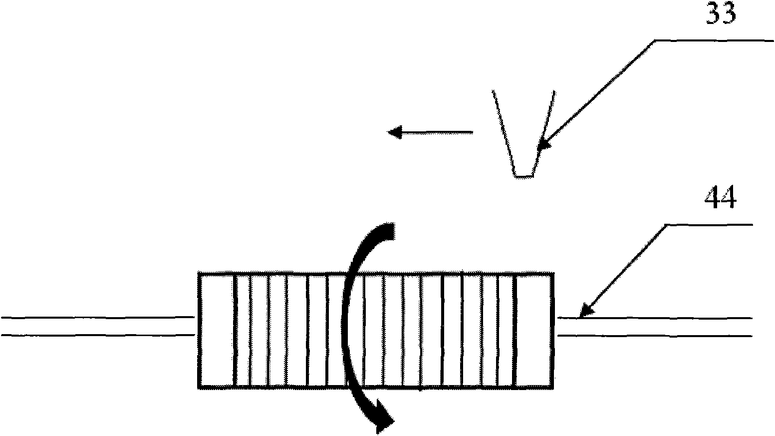
[0035] Step 2: Lift the two ends of the lens column with thimbles (44), the middle is hollow, and make it rotate at high speed along the horizontal line where the thimble is located, and the horizontal direction is stationary, such as image 3 .

[0036] Step 3: Use the high-pressure spray gun (33) to evenly spray the corundum on the lens column, and at the same time, the high-pressure spray gun (33) moves evenly horizontally, such as image 3 . The corundum collides with the lens column, and after spraying, the lens and the wax sticky place are sprayed into a "V" shape, forming a chamfer. The water-sand mixture is used for spraying. The water can cool the heat generated during spraying, and can take aw...

Embodiment 3

[0038] In order to further improve the production efficiency and the smoothness of the surface of the lens column, the step 1 in the embodiment 1 is improved as follows:

[0039] Step 1: Directly bond a plurality of large lenses to be processed and cut them into lens cylinders of required size as a whole. In this step, cutting a plurality of large pieces as a whole greatly improves the production efficiency, and at the same time, the surface of the lens column cut as a whole is smooth, and it is easier to chamfer.


PUM

PropertyMeasurementUnit
thicknessaaaaaaaaaa

Abstract

The invention relates to a chamfering method of an optical lens for a camera. The method comprises the following steps of: firstly, uniformly adhering a plurality of lenses to be chamfered together with wax to form a lens column, and then chamfering the whole lens column; and if the lens is a wafer, polishing the lens into a cylindrical lens column and then chamfering. In the chamfering method, the lens column is uniformly polished with corundum by utilizing different tolerances of the wax and the lens on the corundum, the joint of the lens is polished into a V-shape to form chamfering. The method can be used for carrying out chamfering on a plurality of lenses at the same time and greatly improves the production efficiency.

Description

【Technical field】 [0001] The invention relates to a method for chamfering an optical lens for a camera, in particular to a method for chamfering a small-sized lens. 【technical background】 [0002] In high-quality digital image capture systems such as digital cameras, cameras, projectors, scanners, and camera phones, it is usually necessary to use optical lenses such as optical filters and protective glasses, especially the emergence of mobile phones with cameras. The market demand for optical lenses has increased. In order to improve the cleanliness of the surface of optical lenses and reduce the impact of surface defects on imaging quality, it is necessary to reduce the contact area between optical lenses and the surrounding area, and chamfering optical lenses is to improve their contact area. the best way. However, because the camera is small, the thickness of the optical lens used for the camera is very thin, about 0.145-3.0mm, and the dimensional accuracy is very high. ...

Claims


Application Information

Patent Timeline
Patent Type & Authority Applications(China)
IPC IPC(8): B24C1/04B24C11/00
Inventor 陈丹竹叶清标牛玉香
Owner SHENZHEN O FILM TECH
Why Eureka
Try Eureka