Ejector device having auxiliary-ejection force

A technology of a pushing device and a pushing plate, which is applied to home appliances, other home appliances, and household components, and can solve problems such as time-consuming and ineffective

Active Publication Date: 2011-03-30
ENGEL AUSTRIA
View PDF5 Cites 12 Cited by
  • Summary
  • Abstract
  • Description
  • Claims
  • Application Information

AI Technical Summary

Problems solved by technology

But this is a time-consuming and unproductive process

Method used


Image

  • Ejector device having auxiliary-ejection force
  • Ejector device having auxiliary-ejection force
  • Ejector device having auxiliary-ejection force

Examples


Embodiment Construction

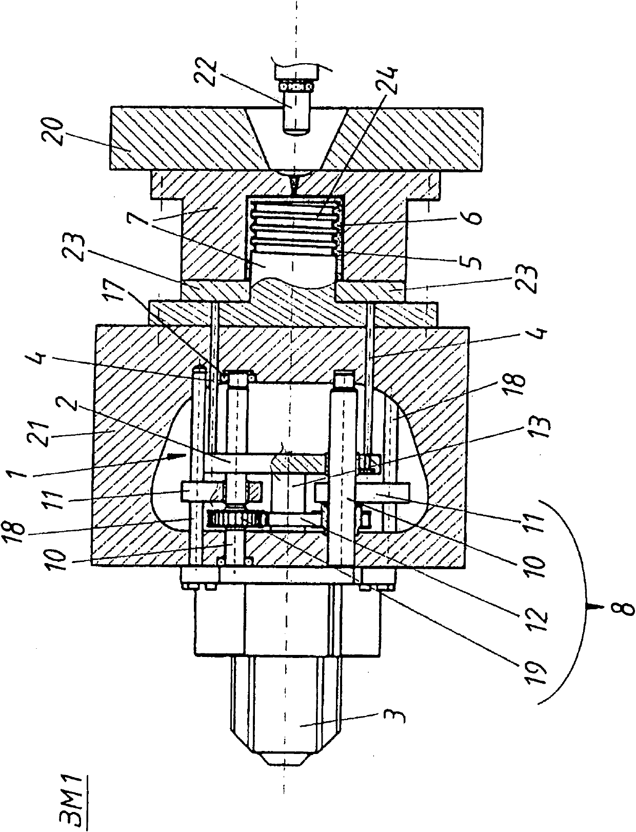
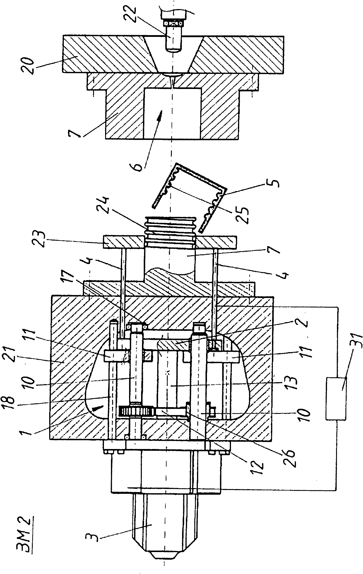
[0021] figure 1 The closed side of an injection molding machine including the ejector device 1 in the first operating mode BM1 is shown. Typically, the closing side of the injection molding machine has a fixed mold clamping plate 20 and a movable mold clamping plate 21 with the two-part injection molding tool 7 arranged between them. Simultaneously formed between the two halves of the injection molding tool 7 is a cavity 6 which, in this view, is filled with the melt which forms the molded part 5 , injected through the injection nozzle 22 .

[0022] The pusher device 1 comprises a drive device 3 which drives the pusher plate 2 in translation via a spindle 13 . A plurality of ejector pins 4 are arranged on the ejector plate 2 through a movable mold clamping plate 21 . At their front end they have ejector pin projections 23 which act directly on the injection molded part 5 and which can be pulled off over the threaded core of the mold half 7 during a translational movement. F...


PUM


Abstract

The invention relates to an ejector device having auxiliary-ejection force, comprising a plurality of ejection pins (4) mounted on a movable ejector plate (2) and driven by a drive device (3) for ejecting injection molded part (5) from a cavity (6) of an injection molding tool (7), wherein the ejector plate (2) is movable with a predetermined normal-ejection force (N) acting the ejecting injection molded part (5) by the drive device (3). A reinforcing device (8) is arranged for reinforcing an ejection force acting on the injection molded parts to an increased auxiliary-ejection force (Z) so as to eject the jammed molded parts (5) by the normal-ejection force (N) that is adjustable by the drive device during existence of the jammed parts (5).

Description

technical field [0001] The invention relates to a pusher device for an injection molding machine, comprising a plurality of push-out pins installed on a movable stacking plate and pushed by a driving device, for pushing out injection molding from a cavity of an injection molding mold Parts, wherein the ejector plate is movable by a drive with a defined nominal ejection force acting on the injection molded part. Background technique [0002] Such devices are used to eject semi-hardened or fully hardened injection molded parts from the cavity. However, especially if the injection-molded product has many indentations, problems can arise when it is pushed out. An example for such an injection molded product is a screw cap for a beverage bottle, which has an internal thread. In order to release it from the female part (with external thread) of the injection molding tool, the ejector pin removes the not yet fully cured injection molding part from one of the mold halves of the in...

Claims


Application Information

Patent Timeline
Patent Type & Authority Applications(China)
IPC IPC(8): B29C45/40
CPCB29C45/2618B29L2031/565B29C45/4407B29C45/4005B29C2045/4031B29C2045/4078
Inventor S·埃皮希
Owner ENGEL AUSTRIA
Why Eureka
Try Eureka