Film deposition device

A film deposition and control device technology, applied in gaseous chemical plating, metal material coating process, coating, etc., can solve the problems of processing chamber pollution and hindering processing, etc.

Inactive Publication Date: 2011-03-30
FUJIFILM CORP
View PDF3 Cites 4 Cited by
  • Summary
  • Abstract
  • Description
  • Claims
  • Application Information

AI Technical Summary

Problems solved by technology

Permeation of this unwanted gas may prevent proper processing or cause contamination of the processing chamber

Method used


Image

  • Film deposition device
  • Film deposition device
  • Film deposition device

Examples


Embodiment 1

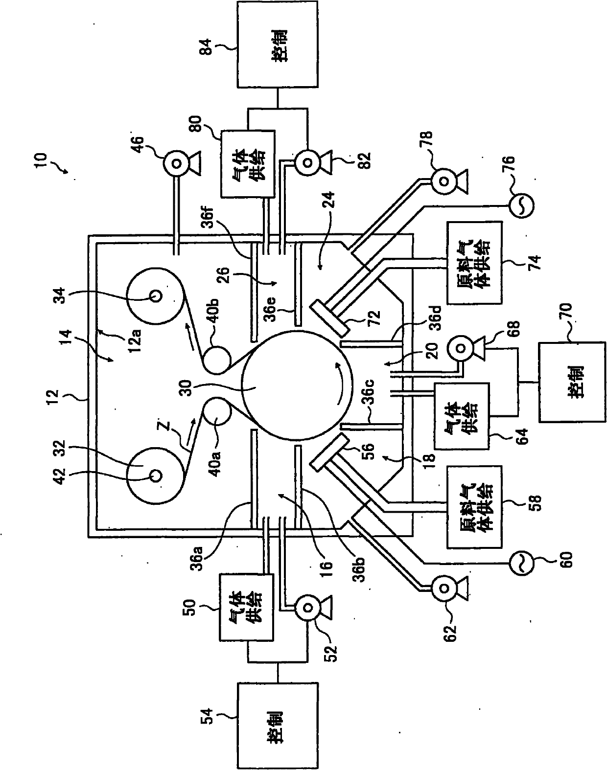
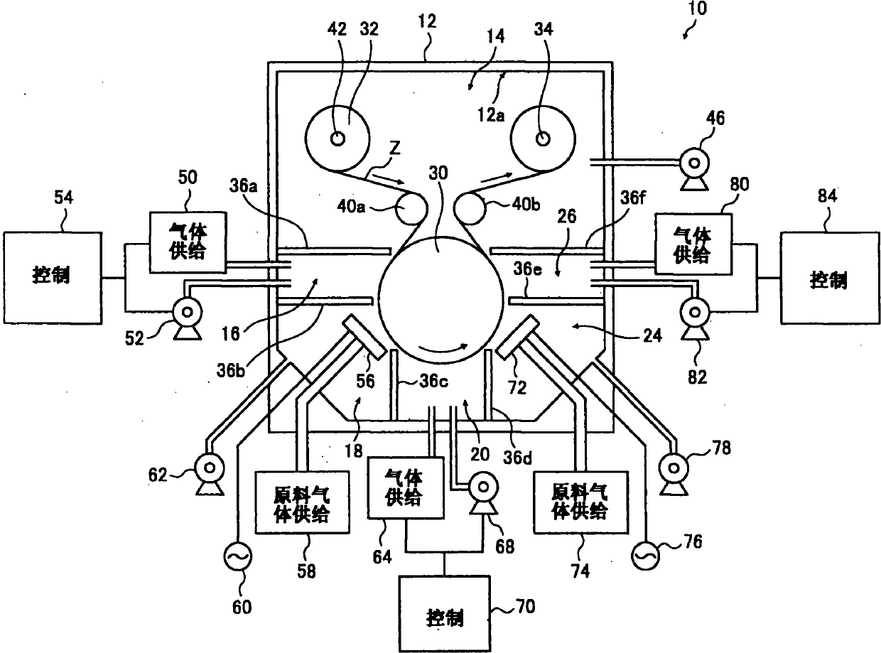
[0127] exist figure 1 The film deposition apparatus 10 shown in is used to deposit a silicon nitride film on a substrate Z.

[0128] The substrate Z used was a PET film (Cosmoshine A4300 available from Toyobo Co., Ltd.).

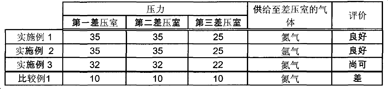
[0129] Silane gas (flow rate of 100 sccm), ammonia gas (flow rate of 100 sccm) and nitrogen gas (flow rate of 800 sccm) were used as raw material gases to form a silicon nitride film by CCP-CVD. The gas used to supply to the differential pressure chamber was nitrogen (flow rate: 1000 sccm).

[0130] The film deposition pressures of the first film deposition chamber 18 and the second film deposition chamber 24 were set to 30Pa and 20Pa, respectively, and the first differential pressure chamber 16 and the second differential pressure chamber 20 were set to a pressure of 35Pa, while the The third differential pressure chamber 26 is set at a pressure of 25 Pa.

[0131] In addition, the power source used was an RF power source with a frequency of 13.56 MHz and...

Embodiment 2 and 3 and comparative example 1

[0134] In Example 2, Example 1 was repeated except that argon gas was introduced into the differential pressure chamber to form a silicon nitride film on a substrate Z having a length of 1000 m, and three differential pressures were visually inspected and evaluated interior of the room.

[0135] In Embodiment 3, in addition to adjusting the amount of evacuation of each differential pressure chamber by the vacuum device to adjust the pressure of the first differential pressure chamber 16 and the second differential pressure chamber 20 to 32Pa, and to adjust the pressure of the third differential pressure chamber The chamber 26 was adjusted out of 22 Pa, Example 1 was repeated, a silicon nitride film was formed on the substrate Z having a length of 1000 m, and the insides of the three differential pressure chambers were visually inspected and evaluated.

[0136] In Comparative Example 1, in addition to adjusting the amount of evacuation of each differential pressure chamber by t...


PUM


Abstract

The film deposition device includes a CVD film forming room disposed on a travel path of a substrate and having a function of performing the film deposition on a substrate by CVD, a treatment room disposed upstream or downstream of the CVD film forming room on the travel path and having a function of performing a predetermined treatment on the substrate, and a differential room disposed between and communicating with the CVD film forming room and the treatment room. The differential room includes a evacuation unit, a gas introducing unit for introducing at least one of a gas to be supplied to both of the CVD film forming room and the treatment room, and an inert gas, and a controller which controls the evacuation unit and the gas introducing unit to keep the differential room at a higher pressure than the CVD film forming room and the treatment room.

Description

technical field [0001] The present invention relates to a film deposition apparatus suitable for preparing a gas barrier film. More particularly, the present invention relates to a film deposition apparatus in which a plurality of processes, including film formation by CVD, are continuously performed as the elongated substrate moves, and which can eliminate the adverse effects of pressure and raw material gas in other process chambers. impact, while also suppressing contamination of the unit by feed gas used in CVD. Background technique [0002] Various functional films (functional sheets), including gas barrier films, protective films and optical films such as optical filters and antireflection films are used in various devices including optical devices, display devices such as liquid crystal displays and organic EL displays, semiconductor devices and thin film solar cells. [0003] These functional films have been produced by film formation (thin film formation) via vacu...

Claims


Application Information

Patent Timeline
Patent Type & Authority Applications(China)
IPC IPC(8): C23C16/54
CPCC23C16/545C23C16/45519
Inventor 藤浪达也高桥伸辅殿原浩二藤绳淳
Owner FUJIFILM CORP
Why Eureka
Try Eureka