Electronic anti-theft lock of rolling door

A technology for electronic anti-theft locks and rolling doors, which is applied in electric alarm locks, building locks, non-mechanical transmission-operated locks, etc. question

Inactive Publication Date: 2013-04-03
罗世同
View PDF0 Cites 0 Cited by
  • Summary
  • Abstract
  • Description
  • Claims
  • Application Information

AI Technical Summary

Problems solved by technology

[0002] The existing rolling door locks cannot prevent illegal opening due to the small number of keys on the lock head and the simple structure of the lock body.
Especially with the characteristics of the rolling shutter door, it is impossible to make the door firm to prevent prying in, so the electronic anti-theft alarm system can only be installed indoors to achieve the purpose of anti-theft
But it is inconvenient to use, because it is necessary to remember to turn on or off the alarm system at all times, otherwise the system will not achieve the purpose of anti-theft as if it is fake

Method used


Image

  • Electronic anti-theft lock of rolling door
  • Electronic anti-theft lock of rolling door
  • Electronic anti-theft lock of rolling door

Examples


Embodiment Construction

[0012] The present invention will be further described below in conjunction with accompanying drawing.

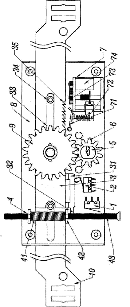
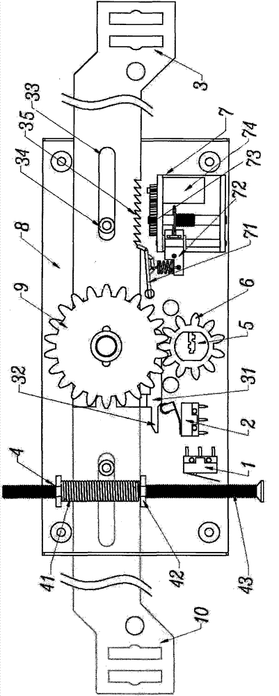
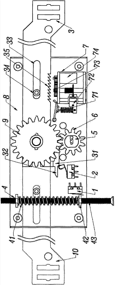
[0013] figure 1 Shown is the schematic diagram of the normal open state of the present invention, figure 2 It is the principle diagram of the illegal opening state of the present invention, image 3 It is the schematic diagram of the state of prying the door of the present invention, Figure 4 Schematic diagram for the external key and lock cylinder, Figure 5 It is a schematic diagram of the connection between the inner key and the main switch. It can be seen from the figure that the present invention includes an upper push plate (3), a lower push plate (10), a lock cylinder (5) and a pinion (6) on the bottom plate (8). And bull gear (9), it is characterized in that: sensor (13) corresponding to sensing chip (11) on the outer key (12) is housed on the lock core (5), sensor (13) is opened control switch ( 2) are connected, the opening control switch (2) is connected wi...


PUM


Abstract

The invention relates to an electronic anti-theft lock of a rolling door, belonging to the classification of locks operated by electricity or magnetic force or controlling special purposes in the international patent classification (IPC) E05B47 / 00 and E05B65 / 00. The electronic anti-theft lock of a rolling door comprises an upper push plate (3), a lower push plate (10), a lock cylinder (5), a pinion (6) and a rack wheel (9) which are mounted on a bottom plate (8), wherein the lock cylinder (5) is provided with a sensor (13) which corresponds to an induction chip (11) on an external key (12); the sensor (13) is connected with an open-control switch (2) through a wireless signal; the on-control switch (2) is connected with an illegal-open preventing device (7); a door-tampering alarm switch (1) is connected with an anti-tampering device (4); and an internal key (14) is connected with a main switch (16) of a control circuit (15). The invention has the functions of preventing illegal door open and automatically giving an alarm during door tampering.

Description

technical field [0001] The invention relates to the classification of special-purpose locks operated or controlled by electricity or magnetic force in E05B47 / 00 and E05B65 / 00 of International Patent Classification (IPC), especially belonging to electronic anti-theft locks for rolling shutter doors. Background technique [0002] The existing rolling door lock cannot prevent illegal opening due to the small number of keys on the lock head and the simple structure of the lock body. Especially the characteristics of the rolling shutter door, it is impossible to make the door firm to prevent prying in, so an electronic anti-theft alarm system can only be installed indoors to achieve the purpose of anti-theft. But it is inconvenient to use, because it is necessary to remember to open or close the alarm system all the time, otherwise the system will fail to achieve the purpose of anti-theft as if it is false. Contents of the invention [0003] The object of the present invention...

Claims


Application Information

Patent Timeline
Patent Type & Authority Patents(China)
IPC IPC(8): E05B47/00E05B45/06E05B17/20E05B65/00
Inventor 王新华陈敏一罗世同张光华黄腾洁张维芳
Owner 罗世同
Why Eureka
Try Eureka