Composite damping single-piston rod viscous damper

A viscous damper and single-piston rod technology, applied in the field of viscous dampers, can solve problems such as structural sloshing, aggravated structure, growth, etc., and achieve the effects of reducing installation space requirements, shortening design length, and improving energy consumption performance

Inactive Publication Date: 2011-03-30
GUANGZHOU UNIVERSITY
View PDF6 Cites 17 Cited by
  • Summary
  • Abstract
  • Description
  • Claims
  • Application Information

AI Technical Summary

Problems solved by technology

However, the above-mentioned invention patent obviously has the following deficiencies: 1. The piston rods running through the two ends of the cylinder, that is, the structure of double piston rods, especially the disc spring group is arranged at one end of the conventional viscous damper, and the whole damper must be extended by at least two times the viscous damping stroke + the thickness of the disc spring group, and the length of the entire damper doubles with the increase of the damping stroke, which will not only make it impossible to install due to space constraints, but even 2. Since the normal working stroke of the damper is a viscous damping stroke, first, when the building structure is just subjected to external force or the external force increases slowly, it will cause the structure to shake or produce excessive The second is that when the external force is a periodic load, although the speed is fast (velocity index is equal to 0~0.3), there is still the defect of aggravating the deformation of the structure at the moment when the external force changes direction; 3. The disc spring Although the group is located in the above-mentioned damping cylinder, it will inevitably be in contact with humid air due to no sealing measures, and it will be corroded over time and will reduce or even lose its elasticity.

Method used


Image

  • Composite damping single-piston rod viscous damper
  • Composite damping single-piston rod viscous damper
  • Composite damping single-piston rod viscous damper

Examples


Embodiment Construction

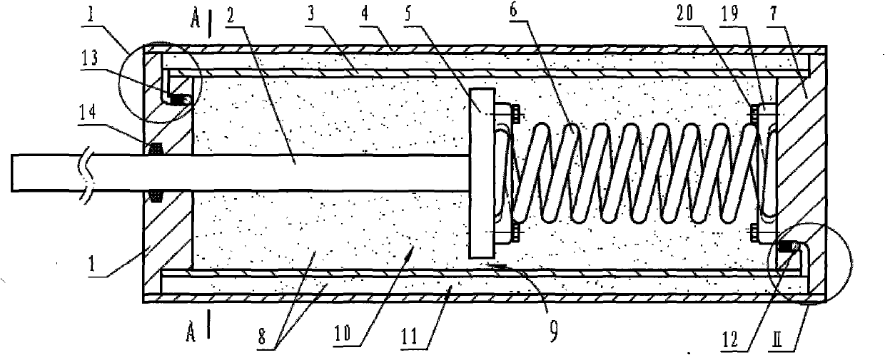
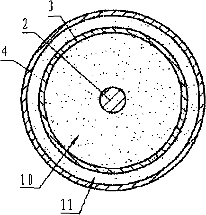
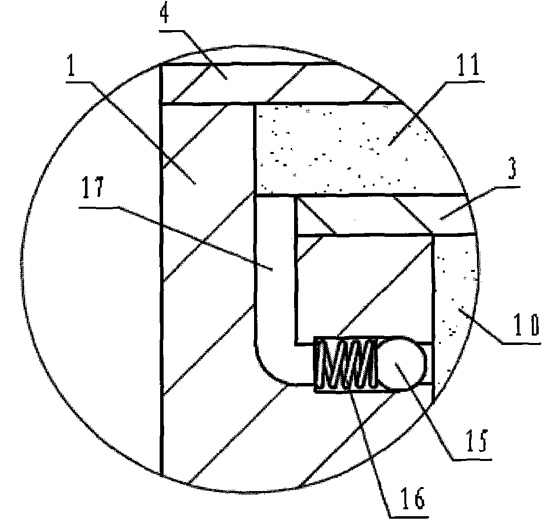
[0020] see Figure 1~4 , the outer cylinder 4 is set outside the inner cylinder 3, and the two ends of the outer cylinder 4 are respectively embedded with a left cylinder cover 1 and a right cylinder cover 7, so that the inner cylinder 3 forms a working cylinder 10, and the inner cylinder 3 and the outer cylinder A compensation cylinder 11 is formed between the cylinders 4; the piston 5 is located in the working cylinder 10, and there is a viscous damping gap 9 between the inner cylinder 3; the piston rod 2 passes through the left end cover 1 through the working cylinder 10 on the left side of the piston 5 , a sealing ring 14 is provided between the piston rod 2 and the left end cover 1; a cylindrical coil spring 6 is provided in the working cylinder 10 on the right side of the piston 5, one end of the spring is clamped on the right end cover by a fixing device, and the other end is held by a fixing device Clamp the end face of the piston 5; the left end cover 1 is provided wi...


PUM


Abstract

The invention relates to a vibration-proof building unit, in particular to a composite damping single-piston rod viscous damper. The damper is a single-piston rod viscous damper and is characterized in that: a piston rod (2) of the single-piston rod viscous damper passes through a left end cover (1) through a working cylinder (10) on the left of a piston (5); a cylindrical spiral spring (60 is arranged in the working cylinder (10) on the right of the piston (5); one end of the spring is fixed on a right end cover (7), while the other end is fixed to the end face of the piston (5); an outer cylinder barrel (4) is sleeved outside an inner cylinder barrel (3) of the working cylinder (10); the left end cover (1) and the right end cover (7) are respectively arranged at two ends of the outer cylinder barrel (4), so that a gap between the inner cylinder barrel (3) and the outer cylinder barrel (4) forms a compensation cylinder (11); one one-way valve (13) is arranged in the body of the left end cover (1); and another one one-way valve (12) is arranged in the body of the right end cover (7). The viscous damper can simultaneously provide viscous damping and elastic damping in the whole moving process of the piston.

Description

technical field [0001] The present invention relates to a vibration or vibration resistant building element, in particular to a motion damper using a liquid as the damping medium, in particular a viscous (also called viscous) damper with a single piston rod passing through one end of a cylinder. Background technique [0002] In terms of structure, the viscous damper is equivalent to a piston cylinder whose working medium is a viscous substance, and is widely used in machinery, construction and other fields. The control mechanism of the viscous damper is to use the working medium to convert part of the energy transferred from the structure into heat energy and dissipate it during the process of compression deformation or high-speed flow, so as to alleviate the impact of external loads, reduce structural vibration, and protect structural safety. the goal of. However, this viscous damper is a speed-dependent damper and has no damping effect on structural deformation caused by ...

Claims


Application Information

Patent Timeline
Patent Type & Authority Applications(China)
IPC IPC(8): F16F13/00
Inventor 周云汪大洋
Owner GUANGZHOU UNIVERSITY
Why Eureka
Try Eureka