
Electric connector

An electrical connector and connection technology, applied in the field of electrical connectors, can solve the problems of increasing the height of the insulating body, miniaturizing the connector, reducing the overall strength of the insulating body, etc., and achieving the effect of increasing the elastic deformation space

Inactive Publication Date: 2012-10-03
FOXCONN (KUNSHAN) COMPUTER CONNECTOR CO LTD +1
View PDF0 Cites 0 Cited by
  • Summary
  • Abstract
  • Description
  • Claims
  • Application Information

AI Technical Summary

Problems solved by technology

[0003] However, in this receptacle connector, since the terminal groove is not provided with a bottom wall, the overall strength of the insulating body is reduced and it is not easy to manufacture, and because the U-shaped contact portion of the terminal needs a deformation space when it is docked with the plug connector, so that Setting the bottom wall must increase the height of the insulating body, which is not conducive to the miniaturization of the connector

Method used


Image

  • Electric connector
  • Electric connector
  • Electric connector

Examples


Embodiment Construction

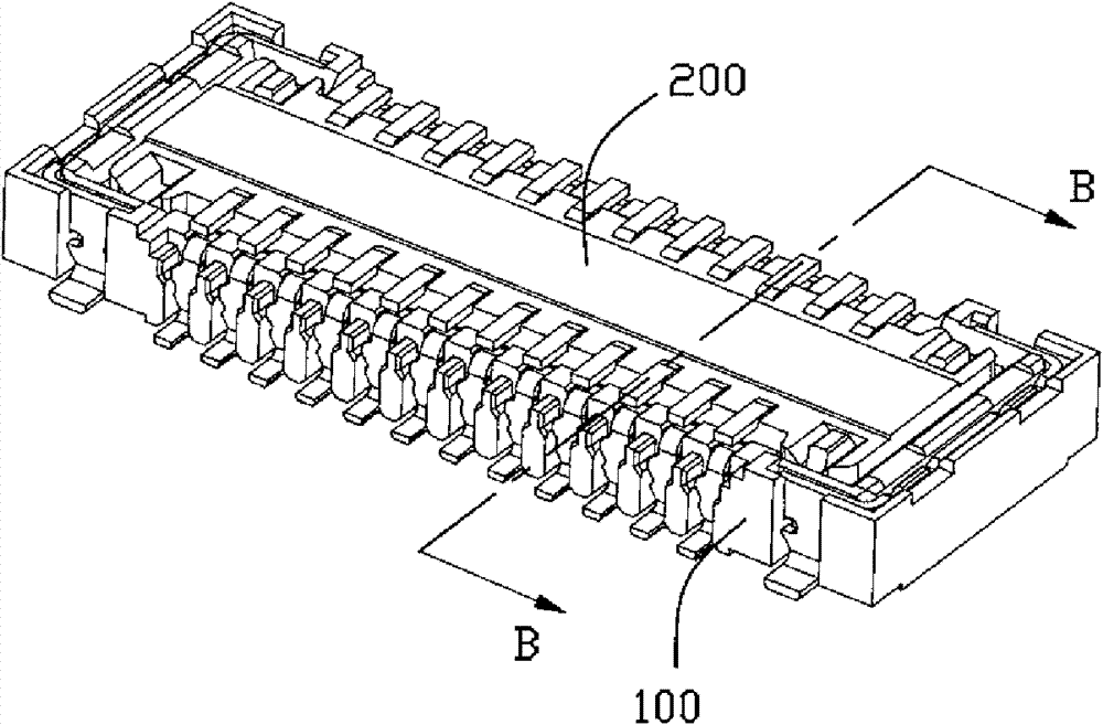
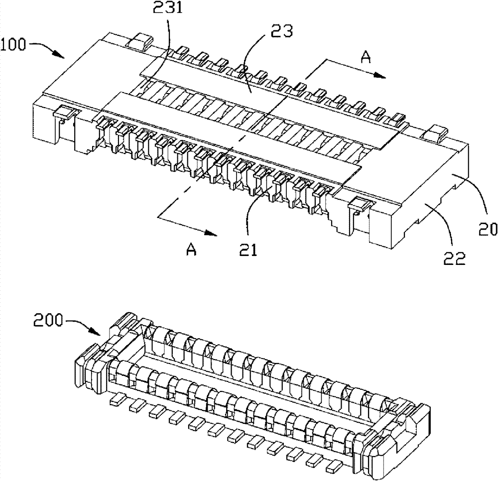
[0015] see figure 1 As shown, the electrical connector 100 of the present invention is installed on a circuit board (not shown) and is used to be mated with the mating connector 200 .

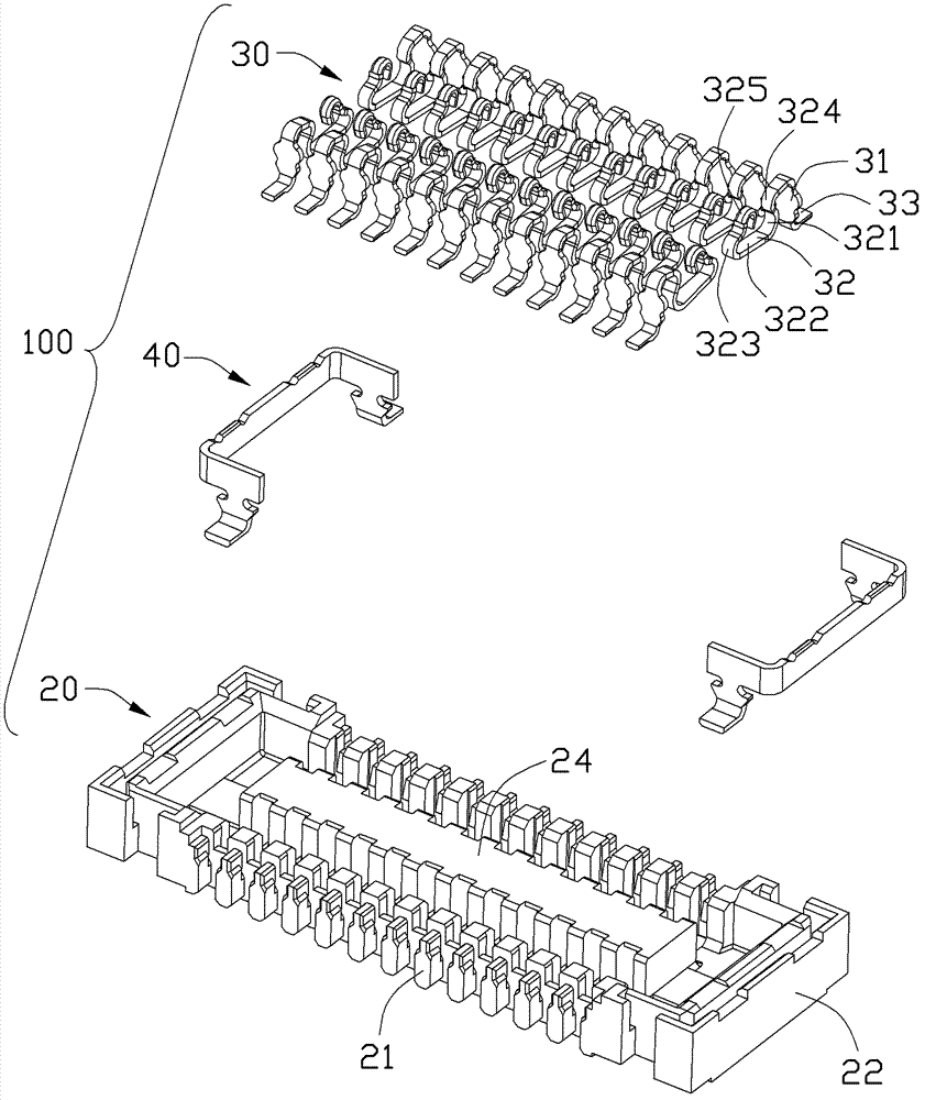
[0016] see figure 2 and image 3 As shown, the electrical connector 100 includes an elongated insulating body 20 , a plurality of terminals 30 accommodated in the insulating body 20 , and fixing pieces 40 fixed at both ends of the insulating body 20 . The insulating body 20 has a pair of side walls 21 arranged in the longitudinal direction, a pair of end walls 22 and a bottom wall 23 located at both ends of the side walls 21, and the side walls 21, the end walls 22 and the bottom wall 23 form a The docking chamber 25 accommodates the docking connector 200 . A plurality of terminal slots 26 for accommodating the terminals 30 are defined in the docking cavity 25 . The side wall 21 has an inner surface 211 facing the docking cavity 25 . A tongue plate 24 protrudes from the bottom wall 23 int...


PUM


Abstract

An electric connector comprises an insulating body and a plurality of terminals housed in the insulating body, wherein the insulating body is provided with side walls and a plurality of terminal slots; the terminal slots are provided with bottom walls; terminals are provided with arms hanging above the bottom walls; the bottom walls are provided with upper surfaces facing the arms; the bottom walls of the insulating body are provided with vias running through the bottom walls; and the upper surfaces of the bottom walls obliquely extend so that the bottom walls become thinner and the height ofthe insulating body can be reduced while providing the deformation space of the arms.

Description

【Technical field】 [0001] The invention relates to an electrical connector, especially an electrical connector with an insulating body having a bottom wall. 【Background technique】 [0002] For example, Taiwan New Patent Publication No. 302787 discloses a board-to-board electrical connector, wherein the receptacle connector has an insulating body and a plurality of terminals accommodated in the insulating body. The insulating body has a receiving chamber for accommodating a plug connector, a tongue plate located in the receiving chamber, and a plurality of terminal slots for accommodating terminals. The terminal has a holding portion fixed on the insulating body, a U-shaped contact portion extending from the holding portion into the receiving cavity, and a welding portion extending from the holding portion out of the insulating body. In order to miniaturize the receptacle connector, the terminal slot penetrates the insulating body up and down, so as to reduce the height of th...

Claims


Application Information

Patent Timeline
Patent Type & Authority Patents(China)
IPC IPC(8): H01R13/40H01R13/11H01R12/71H01R13/115
Inventor 吴俊宽
Owner FOXCONN (KUNSHAN) COMPUTER CONNECTOR CO LTD
Learn More