
Method for aligning a cutter spindle of a granulator and granulator for producing plastic granulate

A granulator and cutter shaft technology, applied in metal processing and other directions, can solve problems such as tool wear, achieve optimal positioning and avoid downtime

Inactive Publication Date: 2011-03-30
KRAUSSMAFFEI BERSTORFF GMBH
View PDF1 Cites 2 Cited by
  • Summary
  • Abstract
  • Description
  • Claims
  • Application Information

AI Technical Summary

Problems solved by technology

This means that there is contact between the tool and the blade and the pressing force is continuously applied, whereby the tool wears out too quickly

Method used


Image

  • Method for aligning a cutter spindle of a granulator and granulator for producing plastic granulate
  • Method for aligning a cutter spindle of a granulator and granulator for producing plastic granulate

Examples


Embodiment Construction

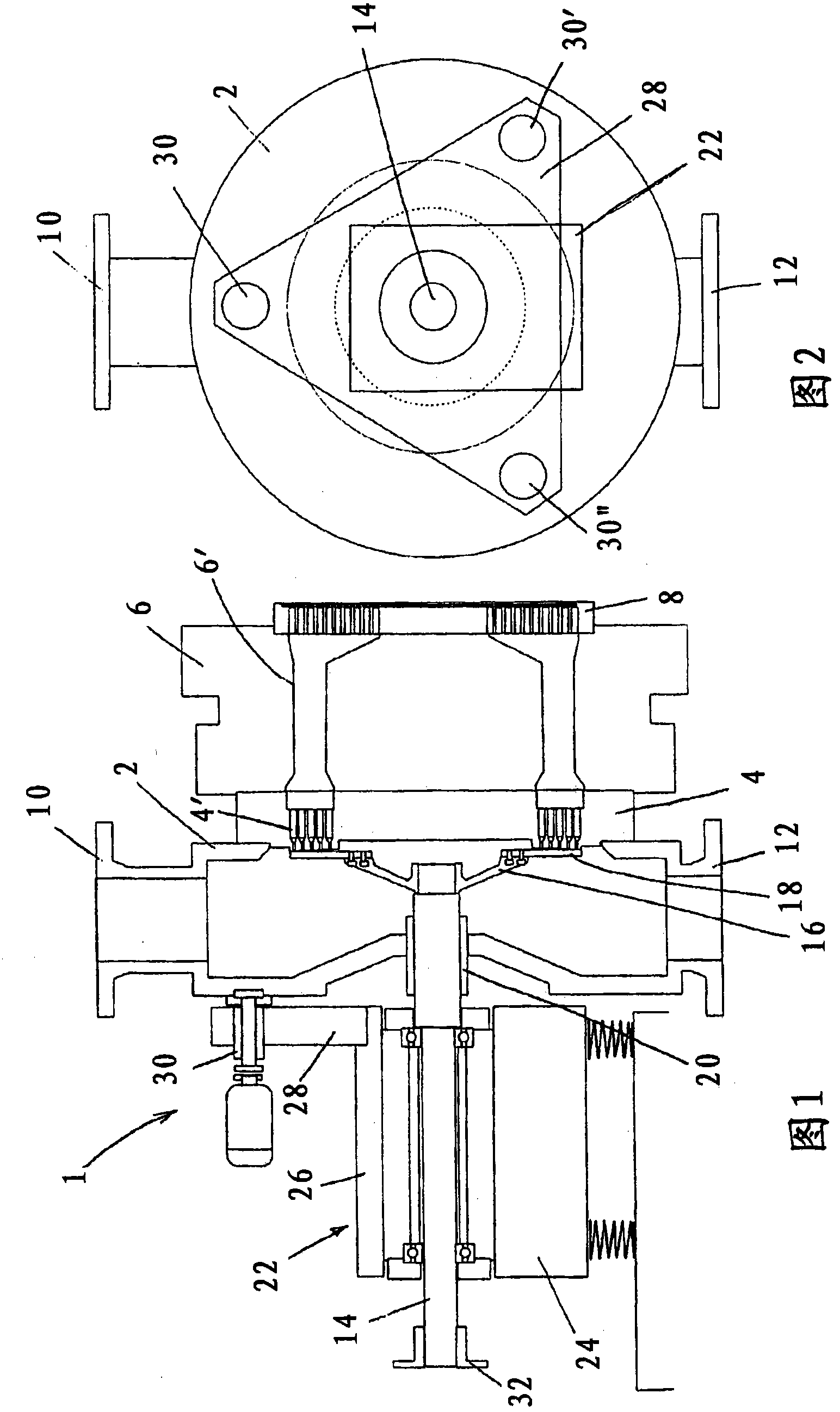
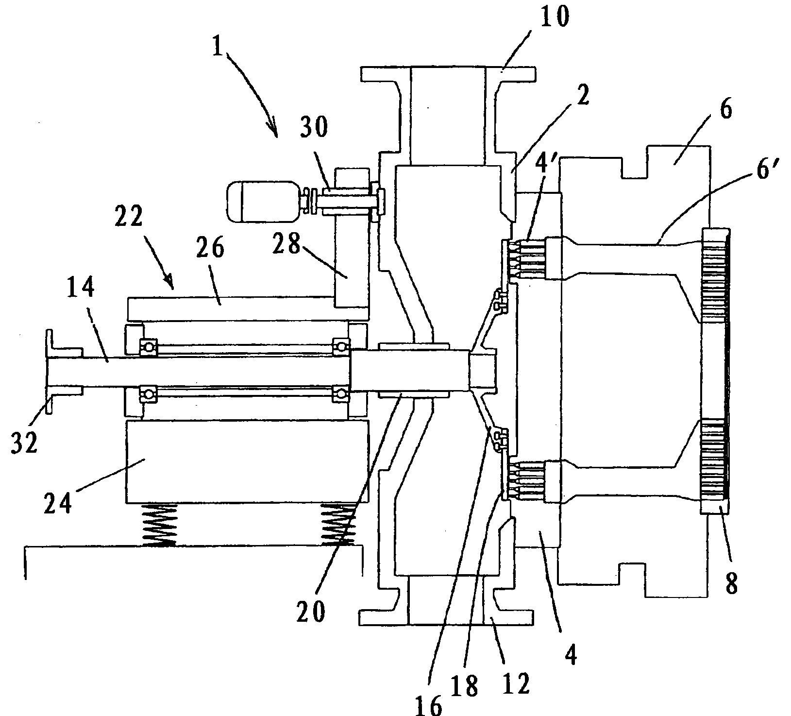
[0043] figure 1 shows a sectional view of an underwater pelletizer with a cutting box 2 in which a tool holder 16 comprising a plurality of knives 18 is rotatably mounted. The knives 18 rotate at a slight to an extremely small distance in front of the blade 4 and the outlet of the plurality of openings 4 ′ provided in the blade. The blade 4 is connected to a nozzle flange 6 of the extruder, not shown. In the nozzle flange 6 a plurality of connecting channels 6 ′ are provided, via which the melt is supplied from the extruder to the respective openings 4 ′ in the blade 4 . Before the melt enters the connecting channels 6', the melt passes through a melt filter 8 in order to remove possible impurities and to avoid clogging of the openings 4'. The cutting box 2 and the blade 4 are fixedly connected to each other, as are the blade 4 and the nozzle flange 6 . The melt discharged in ribbons from the openings 4 ′ is cut off by the rotating knives 18 and forms a granulated product. ...


PUM


Abstract

The present invention relates to a method for aligning a cutter spindle of a granulator, particularly an underwater granulator, relative to a cutting plate (4). As precise an alignment of the cutter spindle is of great significance here for continuous very high to optimal quality of the granulate. According to the invention, such can be achieved by the following steps. Rotationally driving the cutter spindle (14) by means of a drive motor, measuring a force acting on the cutter spindle (14), generating a corresponding signal, and adjusting the alignment and especially the angular alignment of the cutter spindle (14) relative to the cutting plate (4) as a function of the signal. The invention further relates to a granulator, particularly an underwater granulator, for producing plastic granulate, having a cutting box (2) and a cutter spindle (14), a cutter holder rotatably received in the cutting box (2) being mounted thereon and acting together with a cutting plate (4) during operation, and a drive motor that can be connected to the cutter spindle (14), having means for measuring a force acting on the cutter spindle (14), means for generating a corresponding signal, and adjusting means (30, 30', 30'') for adjusting the alignment of the cutter spindle (14) relative to the cutting plate (4) as a function of the signal.

Description

technical field [0001] The invention relates to a method for the positioning of a knife shaft of a pelletizer and in particular an underwater pelletizer relative to the blades. The invention also relates to a pelletizer and in particular an underwater pelletizer for the production of plastic pellets, having a cutting box and a cutter shaft and a drive motor connectable to the cutter shaft, on which the cutter shaft is supported on A tool carrier is rotatably accommodated in the cutting box, wherein the tool carrier interacts with the blade during operation. Background technique [0002] Pelletizers and especially underwater pelletizers are used to manufacture plastic pellets. In this case, the plasticized thermoplastic is extruded by a blade with a plurality of corresponding openings and removed or cut off by a knife passing past the openings, usually held by a knife bar. In the case of an underwater granulator, the thus obtained granulated product in the form of short pla...

Claims


Application Information

Patent Timeline
Patent Type & Authority Applications(China)
IPC IPC(8): B29B9/06
CPCB29B9/065B26D1/38B26D5/00B26D7/2628B29C48/0022B29C48/05B29C48/345B29C48/911
Inventor A·普法伊费尔T·韦伯J·福格特
Owner KRAUSSMAFFEI BERSTORFF GMBH
Learn More