Rock wool pleating machine and pleating method thereof

A pleating machine and rock wool technology, which is applied in the field of material processing, can solve the problems of restricting energy saving in buildings and industries, failing to meet the performance requirements of industrial thermal insulation rock wool products, and poor weather resistance.

Inactive Publication Date: 2011-04-06
NANCHANG UNIV +1
View PDF3 Cites 35 Cited by
  • Summary
  • Abstract
  • Description
  • Claims
  • Application Information

AI Technical Summary

Problems solved by technology

The rock wool products produced by this process do not use pleating technology when the rock wool is paved, so that the rock wool fibers in the product are only arranged in two-dimensional layers in the transverse direction, while the rock wool fibers have no arrangement in the thickness direction of the product. Cloth, that is, there is no three-dimensional overlapping and interlocking of rock wool fibers, so the strength of rock wool products, especially the vertical tensile strength, is very low, which cannot meet the performance requirements of rock wool products used in buildings and other industrial thermal insulation products.
[0003] At present, with the development of the national economy and the implementation of the national energy-saving policy, the demand for high-performance rock wool products for building and industrial thermal insulation is increasing, but most of the rock wool products on the market are low-end products. The product has low strength, poor thermal insulation and poor weather resistance, which restricts the development of building and industrial energy conservation

Method used


Image

  • Rock wool pleating machine and pleating method thereof
  • Rock wool pleating machine and pleating method thereof
  • Rock wool pleating machine and pleating method thereof

Examples


Embodiment 1

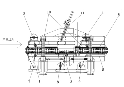
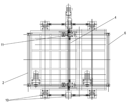
[0017] Example 1. pleating machines, such as Figure 1-3 shown.

[0018] The high-strength rock wool pleating machine described in this embodiment consists of three sets of upper and lower pressing rollers (1, 2 are the first set, 3, 4 are the second set, 5, 6 are the third set) and their driving devices ( 7, 8, 9), the spacing adjustment device 10 between the upper and lower pressure rollers and the tensioning device 11 of the upper pressure roller group of the first group. The first, second and third sets of pressing rollers are connected front and back, and are independently driven by three driving devices 7, 8, and 9, so as to independently control the running speed of each pressing roller set. The pressure roller spacing device 10 is used to adjust the distance between the upper and lower pressure rollers to control the thickness of rock wool products; a set of upper pressure roller tensioning devices 11 is used to adjust and control the opening angle of the first set o...

Embodiment 2

[0019] Example 2. Pleating method

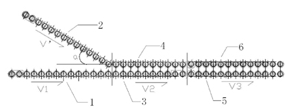
[0020] The rock wool fibers sprayed with adhesive on the surface are spread into a multi-layer rock wool layer with uniform density through the pendulum machine and sent to the pleating machine. The transmission speed V1 of the roller is 15.6m / min, the transmission speed V' of the upper pressing roller is V1 / cos55°=27.2m / min, the transmission speed V2 of the second group of upper and lower pressing rollers is 9m / min, and the third group of upper and lower pressing rollers Transmission speed V3 is 5.2m / min. The first pleat is generated by the difference V1-V2 between the first set and the second set of pressure rollers, and the second pleat is produced by the difference V2-V3 between the second set and the third set of pressure rollers. After the second pleating, the rock wool fiber has a three-dimensional arrangement structure, and is sent to a curing furnace for high-temperature curing and pressed into rock wool products.

[0021] Accord...

Embodiment 3

[0022] Example 3. Pleating method

[0023] The rock wool fibers sprayed with adhesive on the surface are spread into multi-layer rock wool layers with uniform density through the pendulum machine and sent to the pleating machine. The transmission speed V1 of the roller is 15.6m / min, the transmission speed V' of the upper pressing roller is V1 / cos45°=22.06m / min, the transmission speed V2 of the second group of upper and lower pressing rollers is 9m / min, and the third group of upper and lower pressing rollers Transmission speed V3 is 5.2m / min. The first pleat is generated by the difference V1-V2 between the first set and the second set of pressure rollers, and the second pleat is produced by the difference V2-V3 between the second set and the third set of pressure rollers. After the second pleating, the rock wool fiber has a three-dimensional arrangement structure, and is sent to a curing furnace for high-temperature curing and pressed into rock wool products.

[0024] Accord...


PUM

PropertyMeasurementUnit
compressive strengthaaaaaaaaaa
thicknessaaaaaaaaaa
densityaaaaaaaaaa

Abstract

The invention relates to a rock wool pleating machine and a pleating method thereof. The pleating machine comprises three groups of upper and lower compression rollers, driving devices of the compression rollers, a device for adjusting intervals between the upper compression rollers and the lower compression rollers, and a first group of upper compression roller tensioning device, wherein the first group, the second group and the third group of compression rollers are connected in sequence and independently driven. The pleating method comprises the following steps of: spreading rock wool fibers, the surface of which are sprayed with adhesives, into multilayer rock wool which is evenly distributed in density through a pendulum bob machine, feeding the multilayer rock wool into the pleating machine, and adjusting the angle of an dip angle of the first group of upper compression roller of the pleating machine and the difference value of the transmission speeds of the first group of upper compression roller and the second group of lower compression roller of the pleating machine to form a forming fold; subsequently feeding the rock wool subjected to first pleating to the third group, and enabling the rock wool to generate a second differential folding structure by adjusting the transmission speed difference of the third group and the second group of compression rollers; feeding pleated rock wool into a curing furnace, carrying out high-temperature curing and pressing into a rock wool product. In the invention, the high-temperature rock wool product with the pleating coefficient not less than 1: 3 is made, the compression strength of the rock wool product in the 10% deformation amount can reach 40-100KPa, and the perpendicular tensile strength thereof can reach 10-20KPa.

Description

technical field [0001] The invention belongs to the technical field of material processing, and in particular relates to rock wool processing equipment and a production method. Background technique [0002] The existing production process of rock wool products in China is to spread the rock wool fibers formed by the cupola blown wire into a multi-layer rock wool layer with uniform density through a pendulum machine, and then send it into the curing furnace for high temperature curing and press it into rock wool products. . The rock wool products produced by this process do not use pleating technology when the rock wool is paved, so that the rock wool fibers in the product are only arranged in two-dimensional layers in the transverse direction, while the rock wool fibers have no arrangement in the thickness direction of the product. Cloth, that is, there is no three-dimensional overlapping and interlocking of rock wool fibers, so the strength of rock wool products, especiall...

Claims


Application Information

Patent Timeline
Patent Type & Authority Applications(China)
IPC IPC(8): B28B3/12B28B1/52
Inventor 胡明玉赵春燕彭金生丁成平王信刚
Owner NANCHANG UNIV
Why Eureka
Try Eureka