Mobile aerator

An aerator, mobile technology, applied in water aeration, sustainable biological treatment, water/sludge/sewage treatment, etc., can solve the problem of aerator not being movable

Inactive Publication Date: 2011-04-06
HENAN NORMAL UNIV +1
View PDF6 Cites 0 Cited by
  • Summary
  • Abstract
  • Description
  • Claims
  • Application Information

AI Technical Summary

Problems solved by technology

[0002] The motor of the existing aerator driving the impeller pump is fixed on the foundation outside the water surface. The main disadvantage is that

Method used


Image

  • Mobile aerator
  • Mobile aerator
  • Mobile aerator

Examples


Embodiment Construction

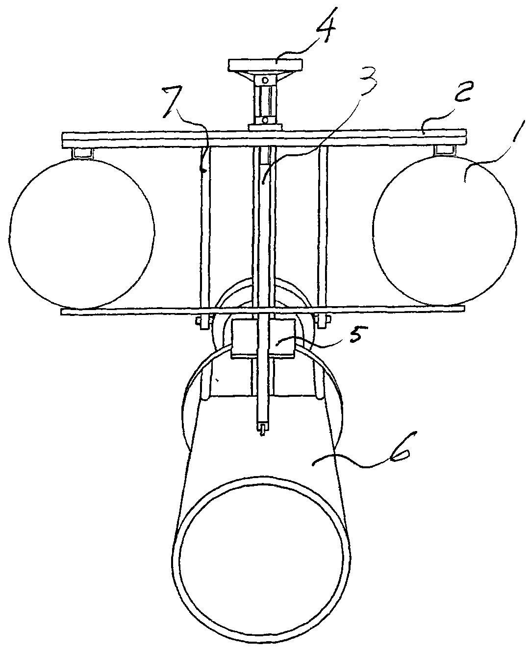
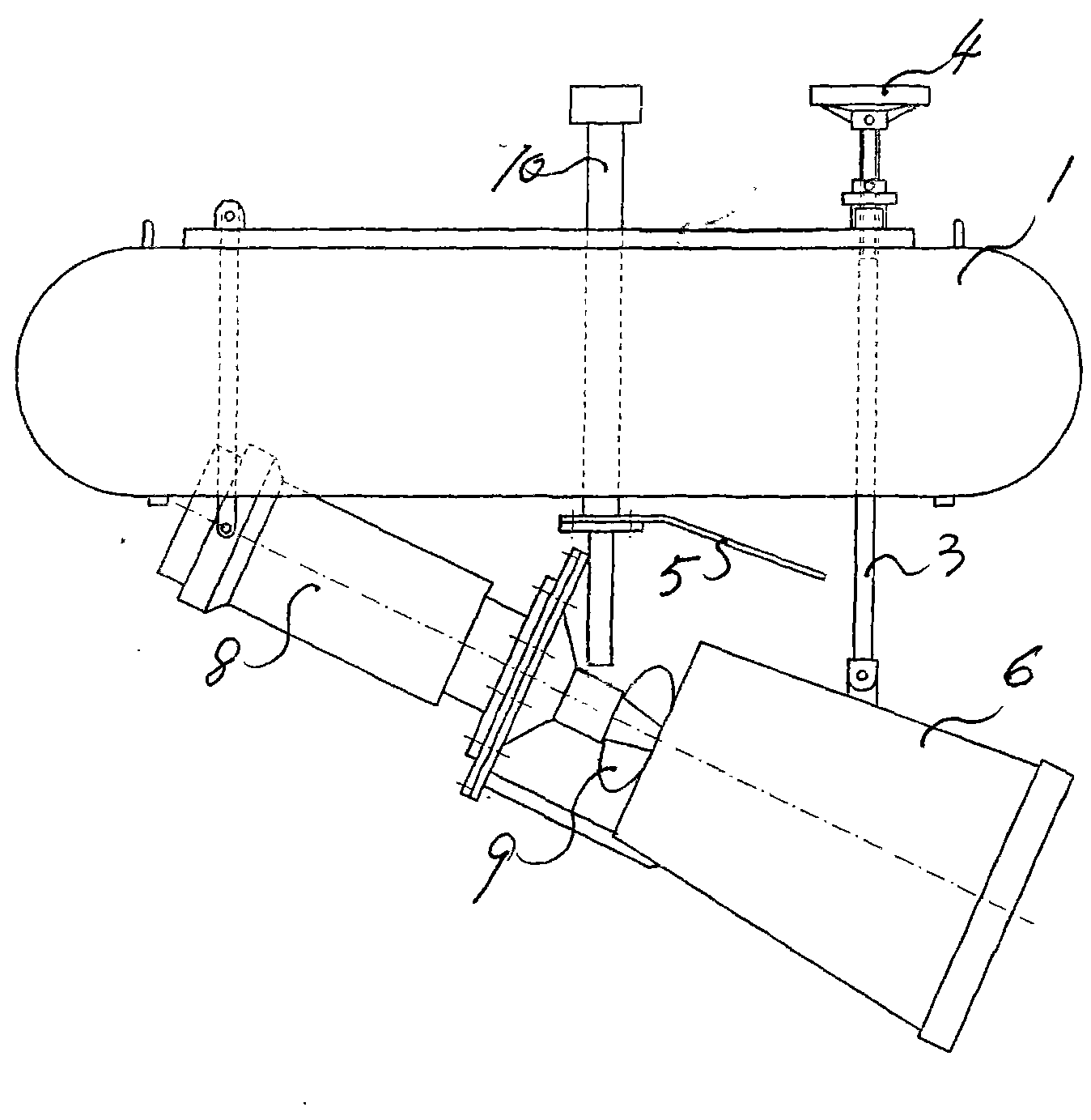
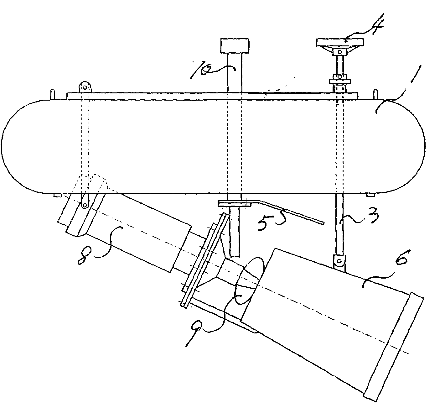
[0005] The present invention is described in detail in conjunction with the following examples, the impeller of the existing aerator is the impeller that horizontal rotation is arranged, and this horizontal impeller is arranged below the surface of the water, and the impeller rotates at high speed to increase oxygen, but the effect of increasing oxygen is not ideal, and Unmovable. The technical measures taken to solve the above problems are, the impeller 9 and the motor 8 of the aerator are placed in the water below the buoy 1, the motor is a submersible motor, and the buoy is two parallel buoys, where the two buoys are in the water. The front part and the rear part are respectively provided with upper and lower connecting plates 2 to make them into a whole. Two connecting rods 7 are arranged in the middle of the upper and lower connecting plates at the rear of the buoy to be hinged with the two sides of the motor casing. Another connecting rod 3 is arranged in the middle of t...


PUM


Abstract

The invention discloses a mobile aerator, relates to sewage treatment equipment and aims at providing a mobile aerator capable of moving. In the technical scheme for achieving the aim, the mobile aerator comprises a motor, an impeller and an aerator, traverse connecting plates are respectively arranged on the front parts and the rear parts of two parallel buoys to connect the two buoys into a whole, a connecting rod connected with a submersible motor is connected with the middle part of the traverse connecting plates on the rear parts of the two buoys, an aeration barrel is connected with the lower end of the other connecting rod, the upper end of the other connecting rod is connected with the middle part of the traverse connecting plates on the front parts of the two buoys, the impeller connected with the submersible motor is arranged on the rear part of the aerator barrel and provided with a front end of a water inlet in the barrel, an air inlet pipe is fixed in the middle parts of the traverse connecting plates in the middle part of the two buoys, the upper port of the air inlet pipe extends out of sewage level, and the lower port of the air inlet pipe is arranged in the aeration barrel behind the impeller. The invention is used for sewage treatment.

Description

Technical field: [0001] The invention relates to a sewage treatment equipment, in particular to a mobile aerator. Background technique: [0002] The motor of the existing aerator to drive the impeller pump is fixed on the foundation outside the water surface. The main disadvantage is that the position of the aerator cannot be moved. However, the location of the aerator often needs to be changed, so this fixed aerator cannot meet the needs. . Invention content: [0003] The object of the present invention is to provide a movable mobile aerator. The technical scheme for realizing the purpose of the present invention is, a mobile aerator, including a motor, an impeller and an aerator, characterized in that: a transverse connecting plate is respectively provided at the front and rear of the two parallel buoys to connect the two parallel buoys. The buoys are connected as a whole, the connecting rod connected with the submersible motor is connected with the middle part of the ...

Claims


Application Information

Patent Timeline
IPC IPC(8): C02F7/00C02F3/02C02F1/74
CPCY02W10/10
Inventor 潘峰黄广道石起增
Owner HENAN NORMAL UNIV
Why Eureka
Try Eureka