Crown spring cage tyep pin and jack component and jack thereof

A hole assembly and crown spring technology, which is applied to the field of in-line spring type jack pin assemblies, can solve the problems of insufficient insertion force, pin out, unreliable insertion of pins and jacks, etc., so as to improve the reliability of use. Effect

Inactive Publication Date: 2011-04-06
CHINA AVIATION OPTICAL-ELECTRICAL TECH CO LTD
View PDF5 Cites 21 Cited by
  • Summary
  • Abstract
  • Description
  • Claims
  • Application Information

AI Technical Summary

Problems solved by technology

[0003] The purpose of the present invention is to provide a crown spring cage pin socket assembly to solve the problem caused by the insufficient insertion and extraction force provided by the crown spring when the crown spring is used to achieve reliable insertion of the pin socket in the prior art. The insertion of the pin and the socket is unreliable, and the pin is easy to come out of the socket in an environment with large vibrations. At the same time, the purpose of the present invention is to provide a socket for the pin and socket assembly.

Method used


Image

  • Crown spring cage tyep pin and jack component and jack thereof
  • Crown spring cage tyep pin and jack component and jack thereof
  • Crown spring cage tyep pin and jack component and jack thereof

Examples


Embodiment Construction

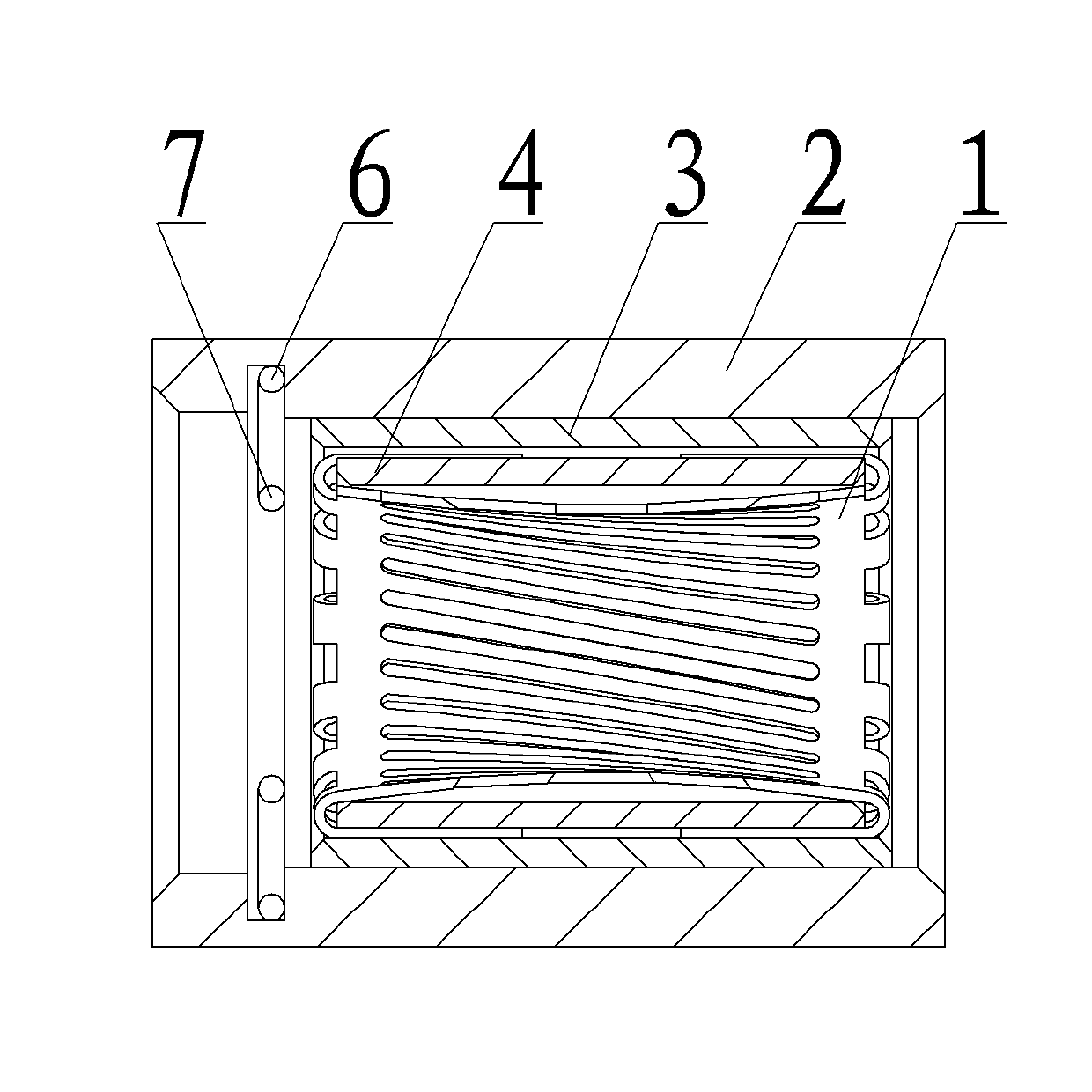
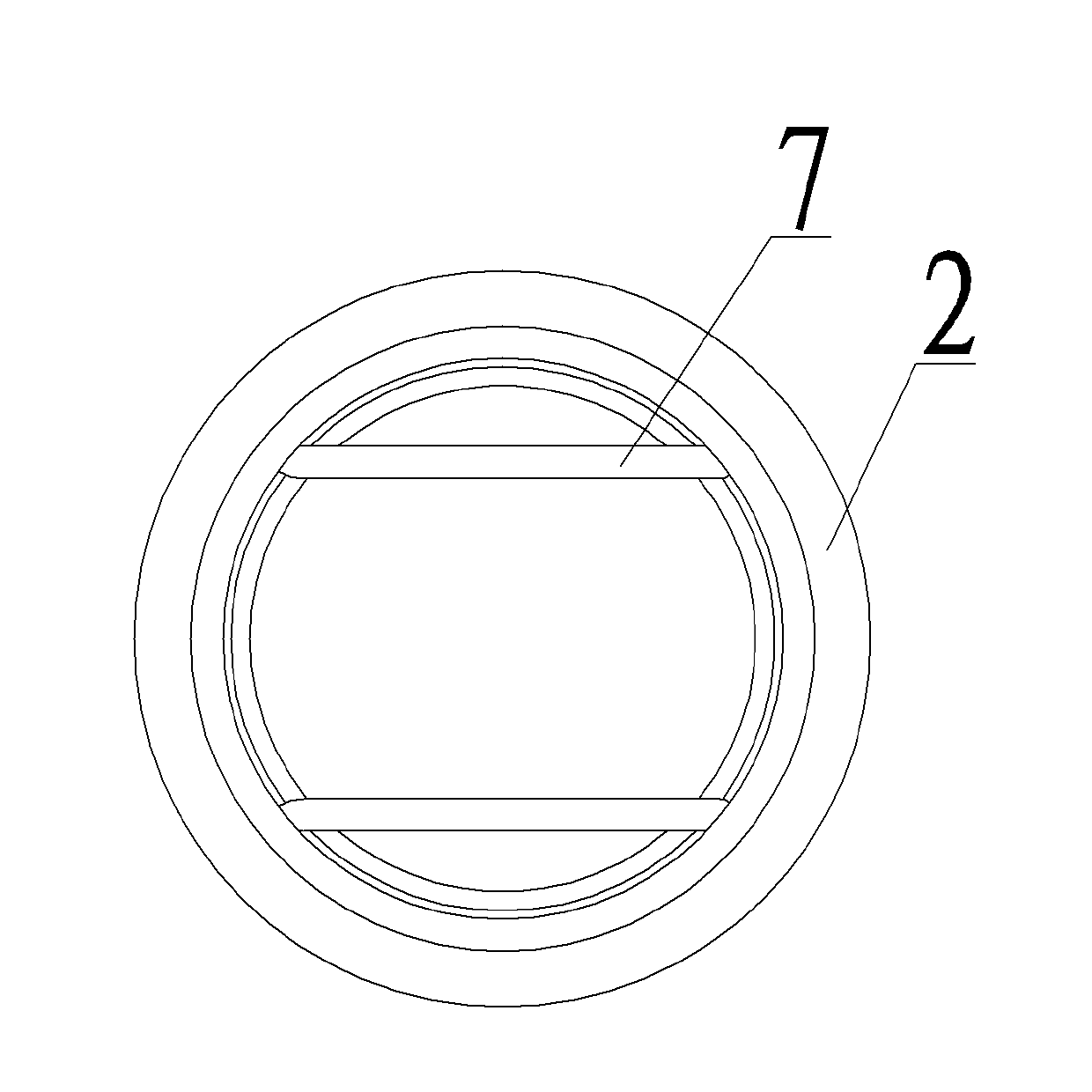
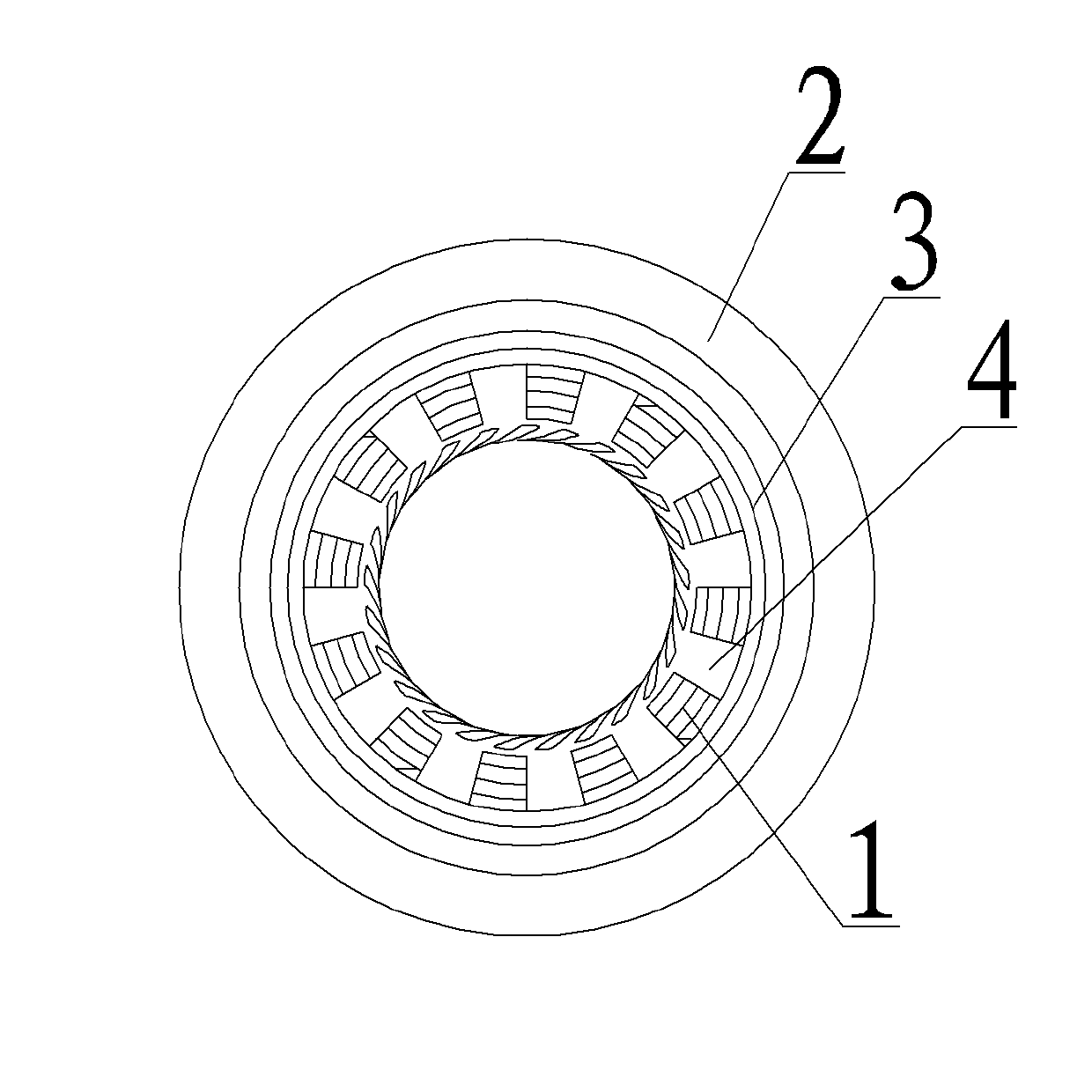
[0026] An embodiment of a crown spring cage pin socket assembly, in Figure 1~7 Among them, the crown spring cage pin jack assembly includes a jack, and a pin 8 is inserted in the jack, and the jack includes an inner sleeve 4, and the outer gap of the inner sleeve 4 is provided with an outer sleeve 3, and the inner sleeve 4 A crown spring 1 is arranged in the inner hole, and the two ends of the crown spring 1 have two end rings 10, and a connecting wire spring bar 11 connecting the two end rings 10 into one is integrally arranged between the two end rings 10, and the two end rings 10 The opposite end face is the inner end face, and the opposite end face is the outer end face. The spaces intersect and are skewed with respect to the axis and form a cage. The outer end faces of both end rings 10 are fixedly connected with outwardly overhanging suspension wire spring bars 12, and the two end rings 10 cooperate with the two ends of the inner hole of the inner sleeve 4, and the sus...


PUM


Abstract

The invention relates to a crown spring cage tyep pin and jack component and a jack thereof. the crown spring cage tyep jack comprises an inner sleeve, wherein an outer sleeve is sleeved outside the inner sleeve, a crown spring penetrates through the inner bore of the inner sleeve; two parallel elastic clamping strips are symmetrically arranged on the port part of the inner bore of the outer sleeve; and the distance between the two elastic clamping strips is less than the minimum internal diameter of the crown spring. The crown spring cage tyep pin and jack component comprises a pin and a jack, wherein the jack contains the inner sleeve; the outer sleeve is sleeved outside the inner sleeve, the crown spring penetrates through the inner bore of the inner sleeve; the two parallel elastic clamping strips are symmetrically arranged on the port part of the inner bore of the outer sleeve, the distance between the two elastic clamping strips is less than the internal diameter of the crown spring; and the pin contains a needle-like connection-peg, and the circumference surface of the needle-like connection-peg is provided with a clamping structure which fits with the two elastic clamping strips in a clamping manner. The elastic clamping strips are arranged on the port part of the jack; and during plugging, the clamping structure on the pin fits with the elastic clamping strips in the clamping manner, thus the reliable plugging of the pin and the jack can be realized and the pin is difficult to separate from the jack.

Description

technical field [0001] The invention relates to a wire spring type socket pin assembly, and at the same time, the invention also relates to the socket of the assembly. Background technique [0002] When designing pins and jacks applied to connectors, for reliable electrical connection between pins and jacks, crown springs are generally provided in the jacks. There are many forms of crown springs, and there are crown bands. The crown band is generally a A thin-walled sleeve set in the socket, with several rectangular grooves arranged on the peripheral surface of the sleeve, these rectangular grooves divide the peripheral wall of the sleeve into several thin strips, and the middle part of these thin strips is recessed toward the axial direction of the sleeve A waist-shaped structure is formed so that when the pin is inserted into the crown spring, the middle part of the crown spring will cling to the pin to achieve a reliable connection between the pin and the socket. The str...

Claims


Application Information

Patent Timeline
Patent Type & Authority Applications(China)
IPC IPC(8): H01R13/04H01R13/187H01R13/213
Inventor 窦红伟吴志富
Owner CHINA AVIATION OPTICAL-ELECTRICAL TECH CO LTD
Why Eureka
Try Eureka