
High-speed electronic connector

A technology of high-speed electronics and connectors, which is applied in the direction of connection, two-part connection device, and parts of the connection device. It can solve the problems of single-ended signal terminal structure without structure, so as to facilitate transmission, reduce crosstalk, and reduce signal transmission. delayed effect

Inactive Publication Date: 2013-06-05
TYCO ELECTRONICS (SHANGHAI) CO LTD
View PDF0 Cites 0 Cited by
  • Summary
  • Abstract
  • Description
  • Claims
  • Application Information

AI Technical Summary

Problems solved by technology

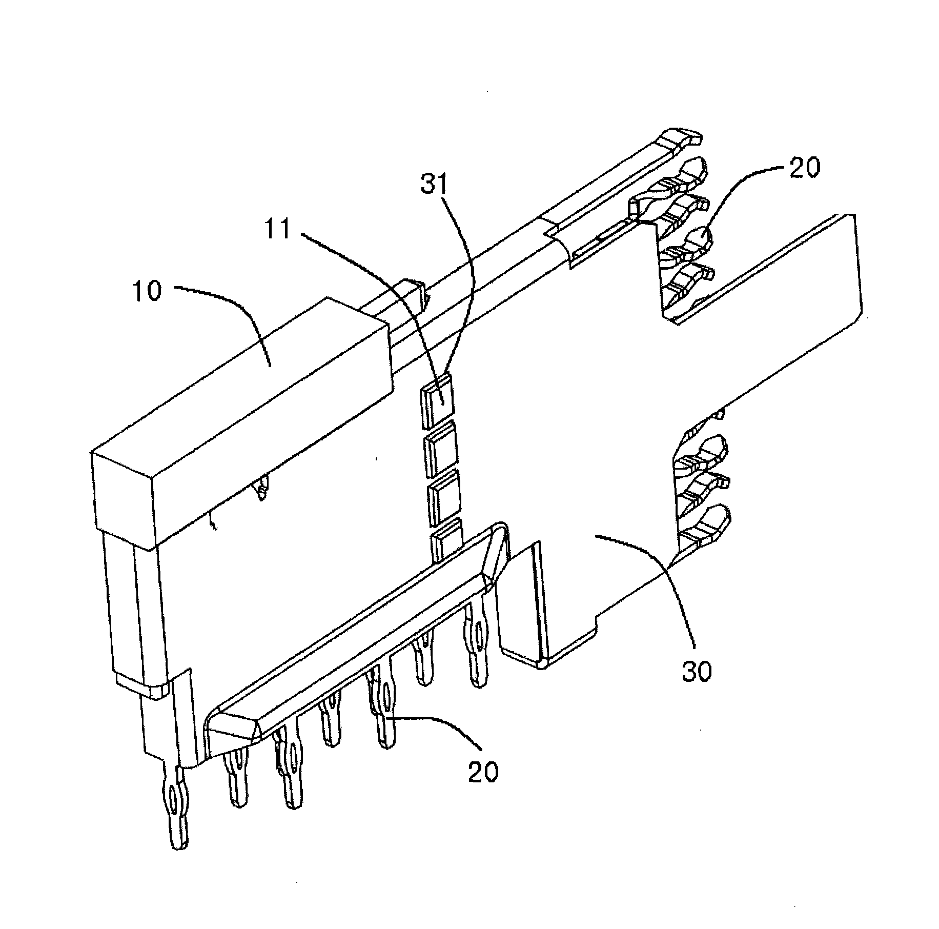
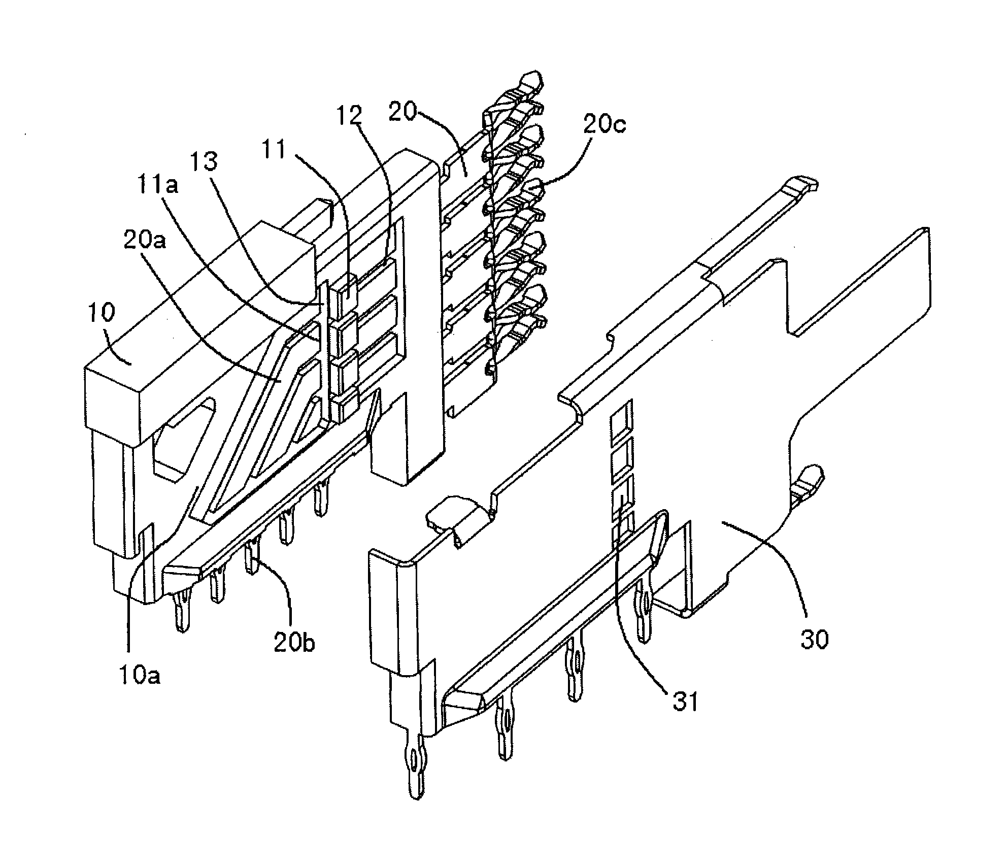
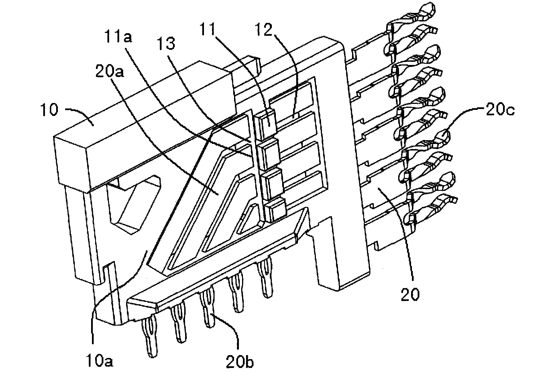
In some known designs, the signal terminals in the high-speed electronic connector are usually embedded in the insulating housing (insert mold), wherein, in order to reduce the crosstalk between the signal terminals, the distance between the signal terminals is usually increased To achieve, and in the existing high-speed electronic connector design, there is usually only a differential signal terminal structure, and there is no single-ended signal terminal structure with a relatively simple structure

Method used


Image

  • High-speed electronic connector
  • High-speed electronic connector
  • High-speed electronic connector

Examples


Embodiment Construction

[0024] The following is a description of specific implementations of the present invention based on specific specific examples. Those skilled in the art can easily understand the structure, advantages and effects of the present invention from the content disclosed in the following examples.

[0025] The present invention can also be implemented or applied by other different specific examples, and various details in this specification can also be based on different viewpoints and applications, and various modifications and changes can be made without departing from the spirit of the creation. Furthermore, the following drawings are simplified schematic diagrams, and only illustrate the basic idea of ​​the present invention in a schematic way. Therefore, the drawings only show the components related to the present invention instead of the number, shape and size of the components in actual implementation. When drawing, the type, quantity, and proportion of each component can be chang...


PUM


Abstract

The connector has terminals (20) i.e. signal terminals, arranged in an insulated housing (10), where the housing has a fixed part and an air-opening part. An earth contact (30) is provided for producing earth shielding and separated from the housing, where the earth contact passes through the terminals. An opening (31) is provided in the earth contact and formed corresponding to the fixed part of the housing. The fixed part has a reinforcing rib, and a projecting partial area (11) is formed at perforation areas of the housing, where the housing has a flat plate assembly.

Description

【Technical Field】 [0001] The invention relates to the field of electronic connectors, in particular to a high-speed electronic connector applied to high-speed electronic signal transmission. 【Background technique】 [0002] In the design of high-speed electronic connectors, the impedance stability of signal terminals and the crosstalk between signals are usually important parameters that affect whether the electronic connector has excellent electrical transmission performance. Therefore, in the existing high-speed electronic In the design of the connector, how to ensure that the signal terminals in the connector maintain a continuous and stable impedance and low crosstalk during signal transmission are technical issues that designers need to consider. In some known designs, the signal terminals in high-speed electronic connectors are usually embedded in an insulating housing (insert mold). In order to reduce the crosstalk between the signal terminals, the distance between the sign...

Claims


Application Information

Patent Timeline
Patent Type & Authority Patents(China)
IPC IPC(8): H01R13/648H01R13/6581H01R13/40
CPCH01R13/6586H01R23/6873H01R23/7073H01R12/724
Inventor 拉皮多特·多伦于乐廷徐锋平内森·J·诺里斯
Owner TYCO ELECTRONICS (SHANGHAI) CO LTD
Learn More