Novel speed reducer with torsion limitation function

A torque-limiting and reducer technology, applied to clutches, automatic clutches, components with teeth, etc., can solve problems such as damage to mechanical equipment parts

Inactive Publication Date: 2011-04-13
张立井
View PDF0 Cites 10 Cited by
  • Summary
  • Abstract
  • Description
  • Claims
  • Application Information

AI Technical Summary

Problems solved by technology

[0003] The purpose of the present invention is to provide a new type of reducer with torque limiting function, which overcomes the defect that the existing reducer has no torque limiting function, and it is easy to cause damage to mechanical equipment parts after overloading

Method used


Image

  • Novel speed reducer with torsion limitation function
  • Novel speed reducer with torsion limitation function

Examples


Embodiment Construction

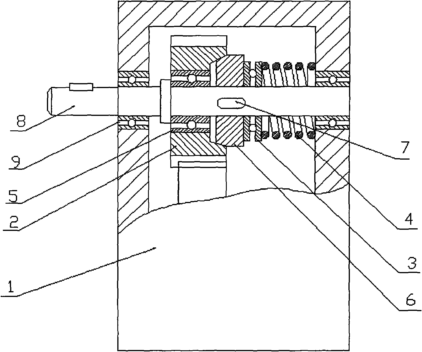
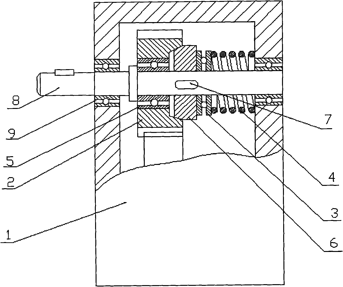
[0009] The final stage gear (2) is installed on the output shaft inside the gearbox (1) through the ordinary bearing (5). ) is installed on the output shaft (8) on the side of the final gear (2). When installing, it must be ensured that the friction disc (6) has the freedom to slide along the axial direction of the output shaft (8) without contact with the output shaft (8) For the degree of freedom of relative rotation, on the side corresponding to the final gear (2) and the friction disc (6), an inner tapered surface with the same taper as the end face of the friction disc (6) is produced, and the two plane bearings (3) are installed at the same time On the top of the output shaft (8), put one of them against the left side of the friction disc (6), and the other one against the inner right side of the gearbox (1) case, A spring (4) is installed on the output shaft (8) between the plane bearings (3), and the spring (4) passes through one of the plane bearings, and the friction...


PUM


Abstract

The invention relates to a novel speed reducer with a torsion limitation function. A final gear is arranged on an output shaft in a gear box through a common bearing, one end surface of a friction disc is conic, and the friction disc is arranged on the output shaft at one side of the final gear through a key. When the friction disc is arranged, the degree of freedom of axially sliding along the output shaft needs to be ensured. An inner conic surface with the same conic degree with the end surface of the friction disc is arranged at one surface of the final gear, which corresponds to the friction disc. Two plane bearings are simultaneously arranged on the output shaft, one of the plane bearings lies against the left side of the friction disc, and the other plane bearing lies against the inner right side of the box body of the gear box. A spring is previously arranged on the output shaft between the two plane bearings, and the friction disc is combined with the final gear by the spring through one plane bearing and the upper conic surface of the friction disc. After the parts are arranged on the output shaft, the output shaft is arranged on the gear box through the bearing of the output shaft.

Description

technical field [0001] The invention relates to a reducer, in particular to a novel reducer with a torque limiting function, belonging to the technical field of mechanical transmission. Background technique [0002] The reducer is an important transmission part in mechanical transmission. At present, in the reducer products, the reducer is only used as a power transmission part. Since there is no torque limiting function, mechanical parts are often damaged after overloading. accident happened. Contents of the invention [0003] The purpose of the present invention is to provide a new type of speed reducer with torque limiting function, which overcomes the defect that the existing speed reducer has no torque limiting function, and it is easy to cause damage to mechanical equipment parts after overloading. [0004] The technical solution adopted by the present invention to achieve the above purpose is: install the final gear on the output shaft inside the gearbox through a ...

Claims


Application Information

Patent Timeline
Patent Type & Authority Applications(China)
IPC IPC(8): F16H57/02F16H35/10F16D43/21
Inventor 张立井
Owner 张立井
Why Eureka
Try Eureka