Lamp bracket

A lamp holder and outer sleeve technology, applied in the field of photographic equipment, can solve the problems of long operation time, adjustment failure, falling back of the inner sleeve, etc., and achieve the effects of large contact area, reasonable coordination and structural improvement.

Active Publication Date: 2011-04-13
余姚市思锐影视器材有限公司 +2
View PDF5 Cites 15 Cited by
  • Summary
  • Abstract
  • Description
  • Claims
  • Application Information

AI Technical Summary

Problems solved by technology

Although this structure has simple advantages, it has the following disadvantages. First, the operation time is tedious, because the pitch of the operating screw matched with the nut is small, so whether it is to release or lock the inner sleeve, it needs to be rotated several times. Second, once the operating screw is screwed into the nut too shallowly, the locking effect of the inner sleeve will be insufficient and the inner sleeve will fall back into the lumen of the outer sleeve, that is, the adjustment will fail. On the contrary, if it is too tight If the operating screw is rotated at a high speed, the metal nut armored in the nut seat will be pushed out of the nut seat due to the reaction force, causing the entire connection mechanism to be scrapped.
The difference between the second structure of the connecting mechanism and the first structure is only that the nut embedded in the aforementioned armored nut seat is omitted, and the thread is directly processed on the inner wall of the nut seat. The nut with such a structure is driven out by the reaction force, but it is prone to another problem of tooth collapse, that is to say, the thread of the inner wall of the nut seat is prone to collapse

Method used


Image

  • Lamp bracket
  • Lamp bracket
  • Lamp bracket

Examples


Embodiment Construction

[0018] In order to enable the examiners of the patent office, especially the public, to understand the technical essence and beneficial effects of the present invention more clearly, the applicant will describe in detail below in conjunction with the accompanying drawings in the form of embodiments, but none of the descriptions of the embodiments is a description of the present invention. Restriction of the inventive solution, any equivalent transformation made according to the concept of the present invention which is only in form but not in substance shall be regarded as the scope of the technical solution of the present invention.

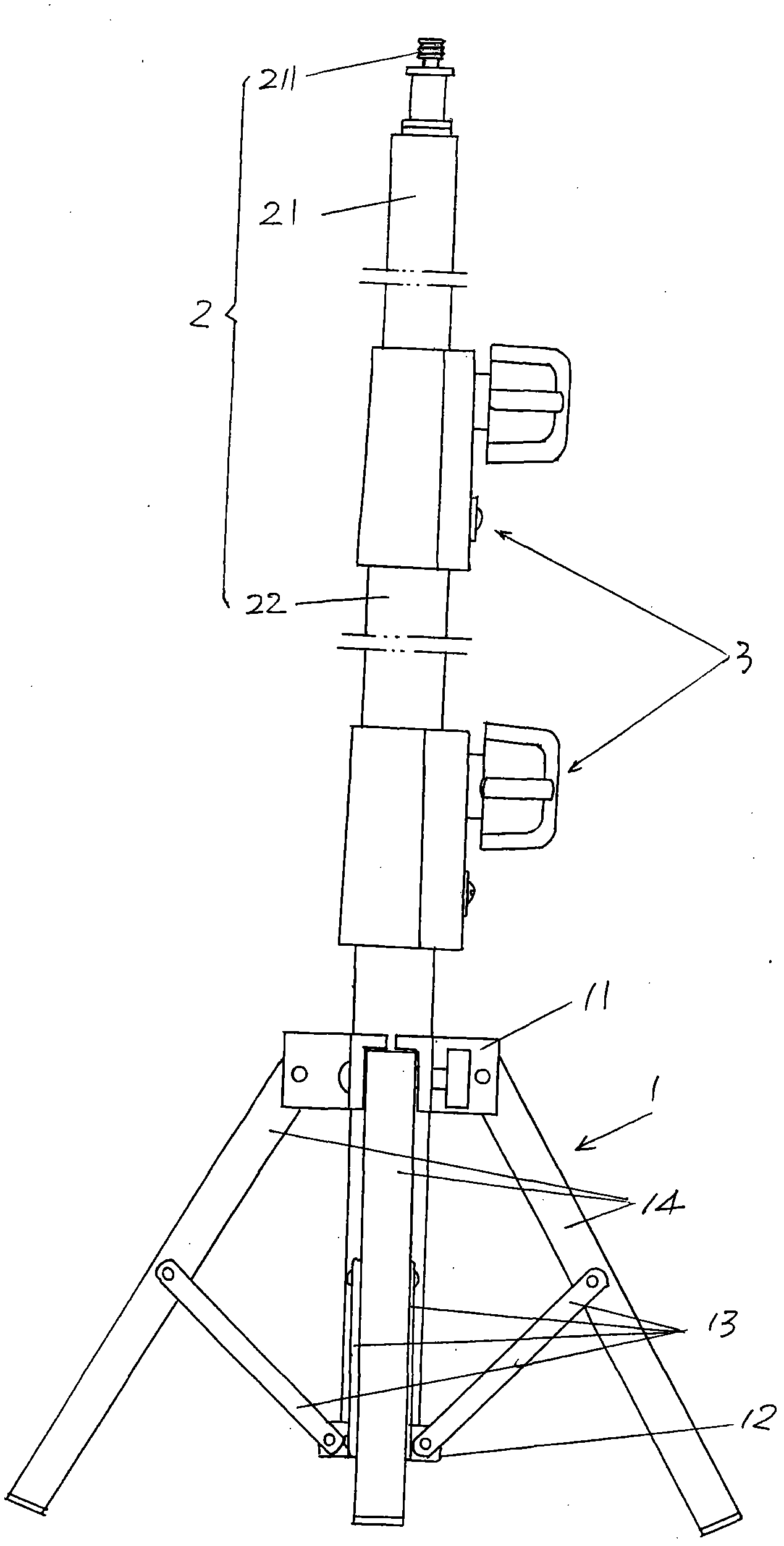
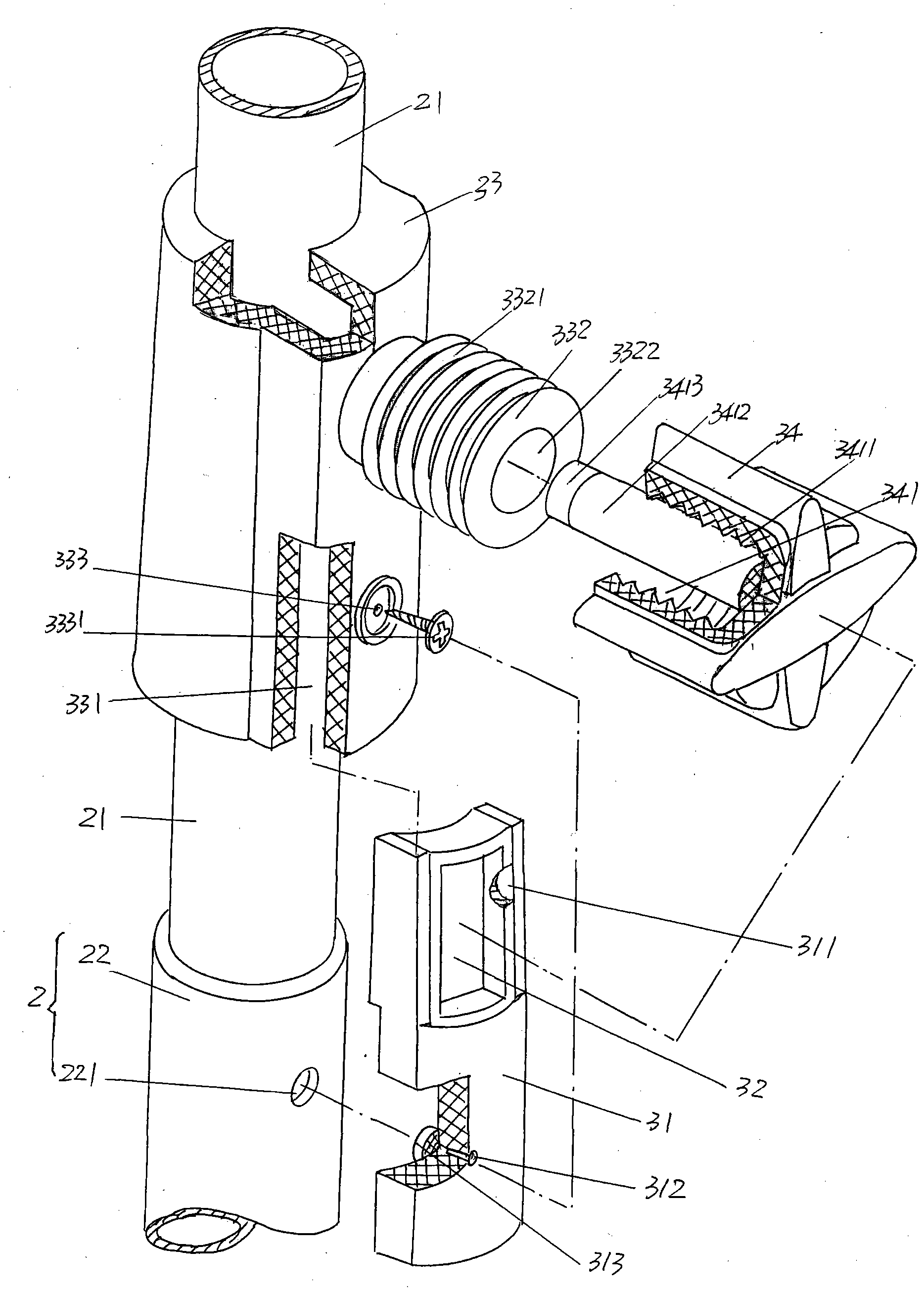
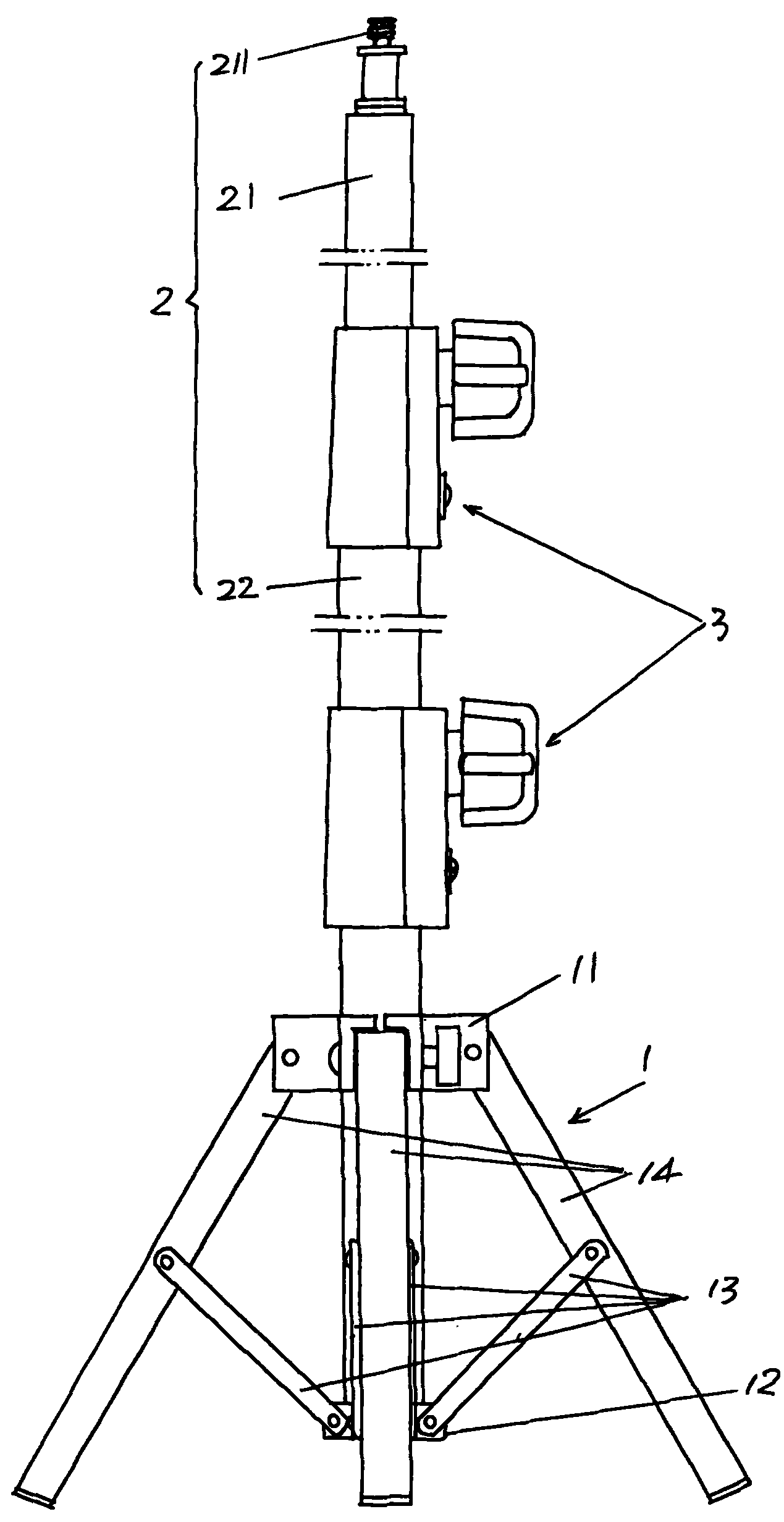
[0019] please see figure 1 , in this embodiment, the given light stand includes a foot support mechanism 1, a casing mechanism 2 that is mated with inner and outer casings 21, 22, and a connecting mechanism 3 that is equal in number to the casing mechanism 2. In the figure, three pipes are shown in total, and the diameters of the three pipes are...


PUM


Abstract

A lamp bracket, belonging to the technical field of photographic equipment, includes a feet supporting mechanism, a sleeve mechanism and a connection mechanism, the lamp bracket is characterized in that the connection mechanism comprises a pressing block frame, a pressing block, a connection bush and a nut, the connection bush is fixed on an external sleeve, a pressing block frame chamber is formed in an accepting chamber of the connection bush, a nut pedestal is extending on an external wall of the connection bush, an external thread is formed on an external wall of the nut pedestal, an axial centre of the nut pedestal is provided with an axial through hole, the nut is provided with a nut chamber, an inner wall of the nut chamber is provided with an inner thread, an axial centre of the nut chamber is provided with a latch column located in the axial through hole, the pressing block frame is in the pressing block frame chamber, a lower end of the pressing block is fixed with a lower end of the connection bush and an upper end of the external sleeve, the pressing block is located in the pressing block chamber at the upper end of the pressing block frame, a lateral face at one side of the pressing block is corresponding to the axial through hole, and the latch column is contacted with the lateral face at one side of the pressing block. The lamp bracket has the following advantages: adjustment for locking or releasing can be quick and easy; and the photographic equipment cannot be damaged.

Description

technical field [0001] The invention belongs to the technical field of photographic equipment, and in particular relates to a lamp stand. Background technique [0002] In photography places, in order to ensure the photographic effect, light stands for carrying lamps are generally equipped, and there is no lack of light stands with various structures in Chinese patent documents. For example, CN2107030U recommends a multi-purpose split flash light stand; CN2376571 has introduced a kind of photography light stand, etc. The lamp holders of the above two patent structures are all proposed for special application occasions. The most widely used light stand in the prior art mainly consists of a base frame (also called a tripod support frame) and a plurality of inner and outer sleeves of a plurality of units arranged on the base frame in a telescopic manner. Between the inner and outer sleeves of each unit Equipped with a connecting mechanism, the connecting mechanism guarantees t...

Claims


Application Information

Patent Timeline
Patent Type & Authority Applications(China)
IPC IPC(8): F21V21/14
Inventor 朱雪忠
Owner 余姚市思锐影视器材有限公司
Why Eureka
Try Eureka