Method for manufacturing multi-layer hollow structure through closed section pipe blank
A hollow structure and closed section technology, which is applied in the field of manufacturing multi-layer hollow structures with closed section tube blanks, can solve the problems of uneven deformation of skin or interlayer, uneven distribution of wall thickness, large local deformation, etc. The effect of mass production, good wall thickness uniformity and high forming accuracy
- Summary
- Abstract
- Description
- Claims
- Application Information
AI Technical Summary
Problems solved by technology
Method used
Image
Examples
specific Embodiment approach 1
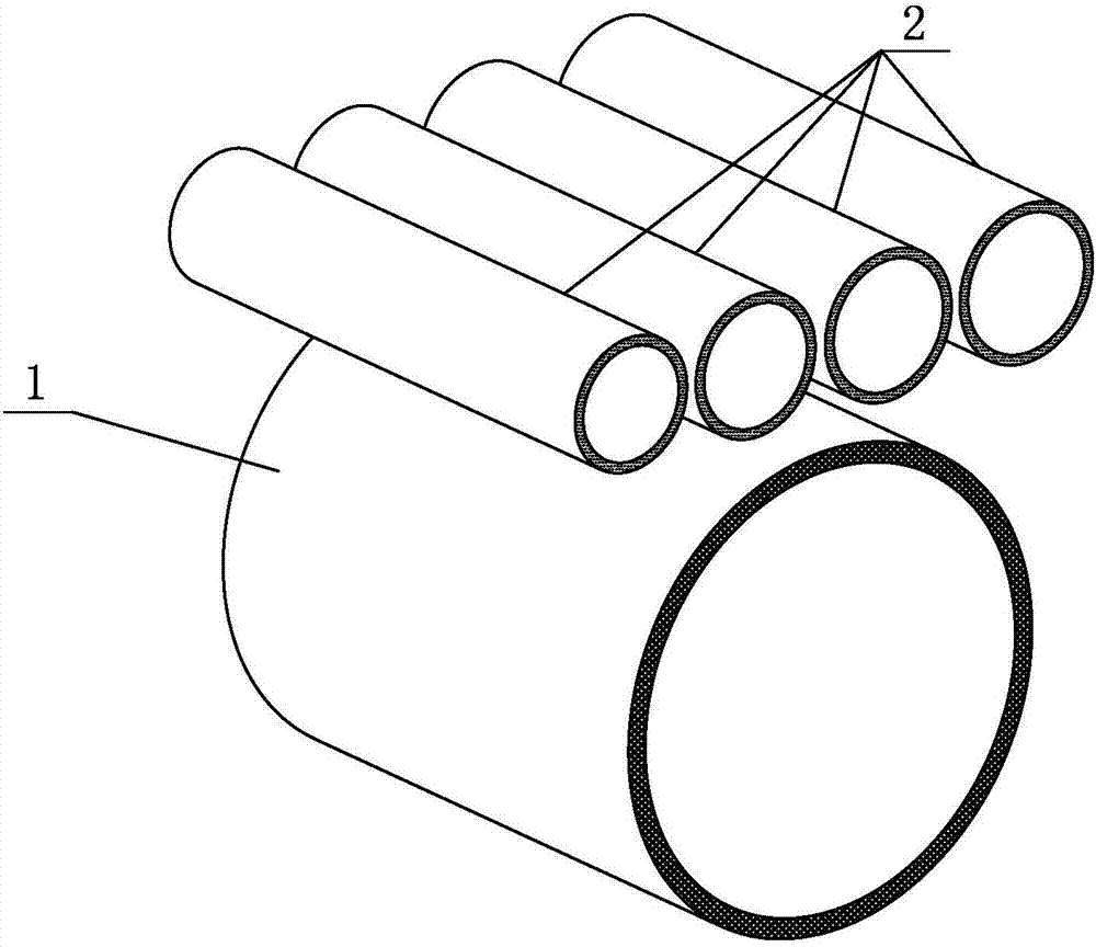
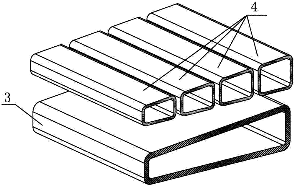
[0047] Specific implementation mode one: combine Figure 1a to Figure 1f and Figure 2a to Figure 2f Explain that the method for manufacturing a multi-layer hollow structure by using a pipe or a plate as a skin and using a pipe as a closed-section tube blank as a core tube is realized through the following steps:
[0048] Step 1. Structural design. According to the load-bearing conditions and technical requirements of the final structure, a reasonable multi-layer hollow structure and its decomposition structure are designed based on the closed-section tube blank;
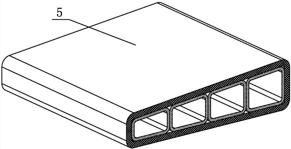
[0049] Step 2, process design, according to the designed multi-layer hollow structure and its decomposition structure, determine the outer skin and inner sandwich core tube prefabricated blank and the corresponding forming process, as well as the outer skin and core tube assembly and connection process, The skin blank 1 adopts a slab or a larger-diameter round-section tube blank, and the core tube blank 2 adopts a ...
specific Embodiment approach 2
[0056] Specific implementation mode two: combination Figure 1a to Figure 1f and Figure 2a to Figure 2f Note, the difference between this embodiment and the specific embodiment one is: for the multi-layer hollow structure with complex shape and internal structure, only use Figure 1b or Figure 2b After simple assembly of the preforms shown, the matching accuracy between the skin preform 1 and the core tube preform 2 cannot meet the conditions required for the subsequent connection. Figure 1c or Figure 2c The assembly structure 5 shown is subjected to secondary shaping, that is, the assembly structure 5 obtained in step 4 is put into the overall preforming mold, and the assembly structure 5 is formed under the joint action of the external rigid mold and internal pressure (liquid or gas). Deformation, the skin preform 3 in the assembly structure 5 and the core tube preform 4 in the assembly structure 5 are further deformed, and the outer skin closely fits the mold cavity ...
specific Embodiment approach 3
[0057] Specific implementation mode three: combination Figure 1a to Figure 1f and Figure 2a to Figure 2f Note that the difference between this embodiment and the second embodiment is that it is difficult to obtain high-precision skin preforms at room temperature for materials with high strength, poor plastic deformation ability, and large rebound at room temperature, such as TC4 titanium alloy. Core tube preform or secondary shaping part 6. At this time, the material can be heated to a suitable temperature, such as TC4 titanium alloy heated to 600-900°C, and then the preform preparation and secondary shaping steps can be performed. Other steps are the same as in the second embodiment.
PUM
| Property | Measurement | Unit |
|---|---|---|
| thickness | aaaaa | aaaaa |
| elongation | aaaaa | aaaaa |
Abstract
Description
Claims
Application Information
 - R&D
- Intellectual Property
- Life Sciences
- Materials
- Tech Scout
- Unparalleled Data Quality
- Higher Quality Content
- 60% Fewer Hallucinations
Browse by: Latest US Patents, China's latest patents, Technical Efficacy Thesaurus, Application Domain, Technology Topic, Popular Technical Reports.
© 2025 PatSnap. All rights reserved.Legal|Privacy policy|Modern Slavery Act Transparency Statement|Sitemap|About US| Contact US: help@patsnap.com


